AM62L: USB VBUS clarification when used for Data Only

Part Number: AM62L

Tool/software:

Hi, 

My assigned focus customer has a question about the USB VBUS pin when you are only transferring data.

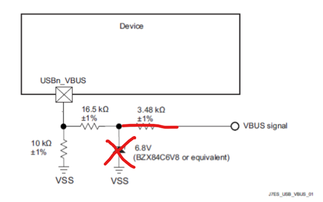
We only provide connections to DP and DM to our own hardware (we don't need to supply any voltage and therefore do not VBUS or DRVVBUS on this connector).  What is the recommendation for this VBUS pin.  I am assuming we can leave it floating and we won't put any of the recommended components in the picture below into the schematic?  Basically no connection to the USBx_VBUS  / DRVBUS.   Let me know if I need to connect anything to these pins for other purposes (like sensing the port is connected).
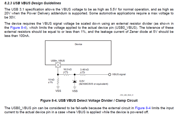
So I read through https://www.ti.com/lit/ug/sprado8/sprado8.pdf  (AM62L (AM62L32, AM62L31) Processor Family Schematic Design Guidelines and Schematic Review Checklist) and it doesn't exactly address this particular use case.  Section 7.x gives some great detail but I couldn't address exactly this scenario.

Can we get some advice?

Best Regards, 

Blake

Thanks!

Blake

  • Hi Blake,

    My assigned focus customer has a question about the USB VBUS pin when you are only transferring data.

    Do you mean their device and the other (their) device are known to be self-powered and it is ok their USB ports to be implemented as custom/non-compliant to USB standard? That is, there will never be a chance someone sometime to plug a USB-compliant device and expect the ports work?

    Thanks,

    Stan

  • Correct, non-compliant to their own hardware with a non-standard connector.  They write:

    USB0 will be a dual role device, and we will use it as a boot option. I think I am fine with the hardware design for USB0 and I’ll follow the guidelines for the VBUS connection for USB0. 

    My concern is about USB1, which will just be a device, not a host. USB1 will go to an off-board connector with only the DP and DM lines. USB1 will not use VBUS to supply any voltage and it will also have no external host supply voltage on VBUS. In such a scenario, my question to TI is what we should do with the USB1 VBUS signal. 

    Hope the question is clear now.

    Thanks!

    Blake

  • Hi Blake,

    Understood. 

    • If the two parts of the system connected via USB are powered from the same power supply -AND- USB cable disconnection never happens during run time---> Connect VBUS sense pin to 5 volts of each system.
    • If the two parts of the system connected via USB have their own power supplies -OR- USB cable disconnection happens during run time---> You will need the fourth conductor for 5-V VBUS and connect VBUS sense as usual. You don't have to source power if haven't to but VBUS sensing is required in this case.

    Hope this helps.

    Regards,

    Stan

  • Hi Stan,

    The customer asks:

    I am not sure I am clear on: 

    If the two parts of the system connected via USB have their own power supplies -OR- USB cable disconnection happens during run time---> You will need the fourth conductor for 5-V VBUS and connect VBUS sense as usual. You don't have to source power if haven't to but VBUS sensing is required in this case. 

    I think the big take away is that TI is saying that VBUS sensing is always needed to be able to use the USB port in any way. Is this correct?

    What exactly is meant by “you will need the fourth conductor for 5-V VBUS?

    I also don’t understand why certain components are crossed out in red in the diagram above. I believe these are there to limit the voltage on the VBUS pin. Why are they crossed out if the statement above says that “… and connect VBUS sense as usual”? Are the crossed-out components not part of the “usual” VBUS connection this device? 

    If VBUS sensing is always needed, I suspect I don’t have to use 5V, I can maybe use 3.3V (or some other lower voltage value) on the VBUS pin. Can you confirm? This would help eliminate the extra expense of providing a 5V rail. 

    Based on the 6.8V Zener diode and the 16.5K + 10K resistors, it seems like TI is trying to limit the voltage on the VBUS pin to 2.6V, and if “VBUS signal” is 5V, then the voltage on the VBUS pin will be about 1.6V. 

    So, if we eliminate the Zener and the 3.48K resistor (change it to 0 Ohm) as shown below, and we supply 1.8V on the VBUS signal, would this do the trick for whatever is needed internally for VBUS sensing and allow the USB port to function? In this case, the voltage on the VBUS pin will be 0.7V. If we supply 3.3V instead of 1.8V on the VBUS signal, then we should have about 1.5V on the VBUS pin. Would this be okay for normal operation of the USB port?

    Thoughts?  I can set up a concall if you would rather.

    Thanks Stan!

  • Hi Blake,

    Ok, I will try to clear out as much as I can.

    I think the big take away is that TI is saying that VBUS sensing is always needed to be able to use the USB port in any way. Is this correct?
    • A self-powered USB device/peripheral detects connection and disconnection events by monitoring the VBUS voltage level. VBUS is considered valid if it rises above 4.75 V and invalid if it falls below 4.35 V. Note this is the actual VBUS value before the resistor division circuit in front of the SoC input. After a divide-by-3 resistor network, it must enter the USBn_VBUS pin.
    • For a USB host, VBUS monitoring is optional.

    Please refer to item 2. in the USB2.0 FAQ

    What exactly is meant by “you will need the fourth conductor for 5-V VBUS?

    I meant you will not able to skip VBUS signal on the connector or in the cable. You will need all 4 pins/signals including D+, D-, VBUS and GND as in a standard USB cable/connectors.

    Also, regarding DRVVBUS,  it is only used in host mode to enable an on-board power switch to turn on the 5 volts VBUS down to the USB device/hub. It is not a signal passed over USB cables.

    I also don’t understand why certain components are crossed out in red in the diagram above. I believe these are there to limit the voltage on the VBUS pin. Why are they crossed out if the statement above says that “… and connect VBUS sense as usual”? Are the crossed-out components not part of the “usual” VBUS connection this device? 

    I meant that VBUS sense/monitoring input (USBn_VBUS) is required to be connected to the VBUS pin of the USB receptacle as usual for USB if you fall to Case 2 (bullet 2). The reason I said this is because your query was is it possible to skip VBUS monitoring function in device mode.

    Crossed out components are required only on USB-C receptacle and with Power Delivery Protocol where VBUS voltages are reaching up to 48 V. As I understand, you will not use VBUS above 5 volts, therefore zenner diode may be omitted and 16.5 and 3.48 ohms may be combined into one resistor. It is however perfectly fine to keep the resistor-zenner network as described in the datasheet.

    If VBUS sensing is always needed, I suspect I don’t have to use 5V, I can maybe use 3.3V (or some other lower voltage value) on the VBUS pin. Can you confirm? This would help eliminate the extra expense of providing a 5V rail.

    There are 2 possibilities here because it is still not clear for me your case:

    1. The USB host is expected to be a USB-compatible host, e.g. a PC, laptop, etc.. In this case, the host will provide 5 volts. Use the resistor divider network described in my above answer (divide-by-3). You will not need any additional 5 volts supply on the device side.
    2. The USB host connected is also your custom project. Here, you can pass 3.3V as a signal from USB host to USB device to indicate the host up and running. You will need to adjust device's side resistor divider. With quick calculations, a divider-by-2 will be fine just like the divider-by-3 with the 5 volts case.
    Based on the 6.8V Zener diode and the 16.5K + 10K resistors, it seems like TI is trying to limit the voltage on the VBUS pin to 2.6V, and if “VBUS signal” is 5V, then the voltage on the VBUS pin will be about 1.6V. 

    Yes ~ 2.6 V and ~1.67 V

    So, if we eliminate the Zener and the 3.48K resistor (change it to 0 Ohm) as shown below, and we supply 1.8V on the VBUS signal, would this do the trick for whatever is needed internally for VBUS sensing and allow the USB port to function? In this case, the voltage on the VBUS pin will be 0.7V. If we supply 3.3V instead of 1.8V on the VBUS signal, then we should have about 1.5V on the VBUS pin. Would this be okay for normal operation of the USB port?

    Sorry for the confusion introduced by the elimination of the 3.48k on the screenshot. Please disregard 3.48k change to 0 ohm. Please refer to my previous comments above.

    Let me know if you have further questions.

    Regards,

    Stan