AM3352: AM3352 Power on leakage

Part Number: AM3352
Other Parts Discussed in Thread: TPS65910, TPS82130

Tool/software:

Hi Expert,

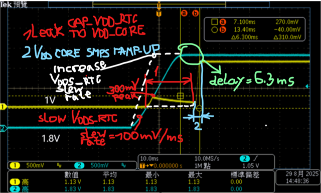
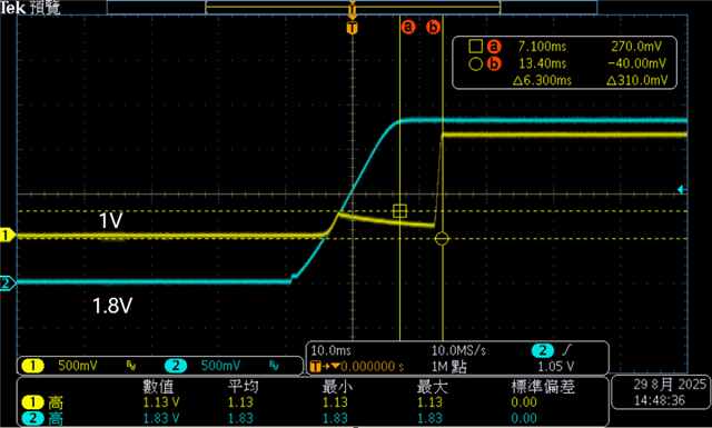
When conducting electrical measurements on the AM3352, it was discovered that the 1.1V power supply of the AM3352 had a leakage problem.

It was confirmed that the 1.8V power supply leaked to the 1.1V_Core power supply. The power sequence requirement in the datasheet is that 1.8V must rise before 1.1V.

According to the datasheet, there's a slight current leakage (surge) at 1.1V when the 1.8V voltage rises. Does this current leakage (surge) have any impact? Is there any solution?

Thanks

Daniel

  • Hello Daniel,

    According to the datasheet, there's a slight current leakage (surge) at 1.1V when the 1.8V voltage rises. Does this current leakage (surge) have any impact? Is there any solution?

    From mentioning  the notes on VDD_CORE additional leakage current, available in the section Power Supplies of the  AM3352 Datasheet., I understand that when you refer to 1.8 V power supply you actually mean the AM3352 VDDS_RTC 1.8V power supply. Please correct me if this is not the case, as my below analysis considers the VDDS_RTC to be the 1.8V power supply depicted in your waveforms.

    From your image 2, I can see that the VDDS_RTC is started about 5 ms earlier than the VDD_CORE. According to the notes, there should be no increase in VDD_CORE leakage when VDDS_RTC started before VDD_CORE. 

    The below thread describes a resolved similar issue in the past (the observed shape of VDD_CORE very similar):

    AM3354 VDD_CORE abnormal ramp-up issue

    The above thread refers to the case in which:

    The internal RTC LDO of the SoC is disabled, having AM3352 RTC_KALDO_ENn input (active low) tied to the VDDS_RTC. In this case the AM3352 CAP_VDD_RTC pin is used as input to which 1.1V power supply from the VDD_CORE is  applied.   

    This configuration is described in the section Power Supplies, Note B under the table Power-Supply Sequencing With Internal RTC LDO Disabled of the AM3352 Datasheet

    As a summary from the thread, If you have the CAP_VDD_RTC pin of the AM3352 SoC tied to the VDD_CORE, and RTC_KALDO_ENn tied to the VDDS_RTC, the following happens:

    As per your waveform 2, the VDDS_RTC rises relatively slowly. Within 5 ms from its initial ramp-up, the VDDS_RTC reached 500mV, so it is still interpreted as a logic Low at the RTC_KALDO_ENn input when VDD_CORE starts to power-up. The RTC_KALDO_ENn=0 activates the SoC internal RTC LDO. The CAP_VDD_RTC pin is the output of the enabled internal LDO. Because CAP_VDD_RTC is externally tied to the VDD_CORE, there is a bus contention between both power supplies for several milliseconds, until RTC_KALDO_ENn = 1 which enables pin CAP_VDD_RTC again as input. 

    According to the above thread, such a bus contention causes the observed ditch in the VDD_CORE power supply.

    With such a schematic configuration, a possible solution is to use a  VDDS_RTC with a faster slew rate - recommendation is < 0.1 V/uS according to section Power Supplies/ subsection Power Supply Slew Rate Requirement of the AM3352 Datasheet

    Please check if the PMIC you use has NO soft start enabled on the VDDS_RTC. Do you have options to insert a larger delay between VDDS_RTC and VDD_CORE ?

    I hope this thread helps you find a solution.

    Kind Regards,
    Anastas Yordanov

  • Hi Expert,

    What practical impact does this phenomenon have on the IC?
    You mentioned increasing the delay between VDDS_RTC and VDD_CORE. How long would this delay be?
    =>Do you have options to insert a larger delay between VDDS_RTC and VDD_CORE?

    Thanks

    Daniel

  • Hi Daniel,

    What practical impact does this phenomenon have on the IC?

    I need to internally consult and confirm  with another expert regarding any risks associated  with such transient CAP_VDD_RTC enabling as output when it is expected to be input at which VDD_CORE is applied.

    You mentioned increasing the delay between VDDS_RTC and VDD_CORE. How long would this delay be?
    =>Do you have options to insert a larger delay between VDDS_RTC and VDD_CORE?


    I think I made a wrong assumption in my previous analysis that VDD_CORE ramps-up earlier. (I will explain in a follow-up analysis.) On your waveform it is seen that the VDD_CORE reaches nominal value (1.1V) about 6.3 ms after VDDS_RTC setups to 1.8V. And this delay shall be sufficient.

    Kind Regards,

    Anastas Yordanov

  • Hi Daniel,

    In my previous analysis I had mistaken the initial 300 mV rise of the VDD_CORE with the actual VDD_CORE ramp-up. According the second customer waveform, the actual VDD_CORE ramp-up (stage 2 on diagram below) happens 6.3 ms after VDDS_RTC has setup to 1.8V. So by mistake I spoke about a bus contention between the "activated" PMIC's VDD_CORE SMPS output and the enabled (for a short time) SoC internal LDO CAP_VDD_RTC output. The thread that I provided as an example:

    AM3354 VDD_CORE abnormal ramp-up issue

    has the following explanation of the initial 300 mV rise of VDD_CORE and the ditch that follows (stage 1 in the diagram):

    "As before VDDS_RTC is ramp up to 1.8V, the RTC_KALDO_ENn is low which means that RTC internal LDO is enabled, is it possible that RTC internal LDO source (VDDS_RTC? need your double confirmation as below question #3)  have leakage current to CAP_VDD_RTC pin, then CAP_VDD_RTC/VDD_CORE have a small ramp up , and after VDDS_RTC is ramp up to 1.8V,  the RTC_KALDO_ENn is high which means that RTC internal LDO is disabled, and VDDS_RTC leakage current is cut off and CAP_VDD_RTC/VDD_CORE power rail abnormal level is dropped, and then real VDD_CORE power rail ramp up, so from wave form, looks like there is ditch."

    Generally speaking, the observed ditch in VDD_CORE curve is because of the transient current leak between the CAP_VDD_RTC  output to the deactivated PMIC VDD_CORE SMPS output. 


    According to the datasheet, there's a slight current leakage (surge) at 1.1V when the 1.8V voltage rises. Does this current leakage (surge) have any impact? Is there any solution?

    Ans. 1: Here is the excerpt from the AM3354 VDD_CORE abnormal ramp-up issue  that provides the solution (the ditch in VDD_CORE reported to be no longer observed):

    "The problem is closed now. It is not due to power up sequence, the power up sequence of customer design is completely same as TPS65910, VDDS is the first rail in sequence.

    Finally we find it is related to the soft start feature of TPS82130. The ramping up of 1.8V generated by TPS82130 is much slower than TPS65910 due to soft start. It seems the leakage from 1.8v to 1.1v can be eliminated once 1.8V rail ramping up fast enough. The glitch on 1.1v completely disappeared once we disable the soft start feature of 1.8V DC/DC."

    I suspect that in your case the VDDS_RTC having slew rate of approx. 100 mV / ms is too slow.

    Once again, is it possible that you use a PMIC with soft start enabled ?

    Ans. 2: To be able to analyze the impact of the current leakage from VDDS_RTC (1.8V) to the VDD_CORE(1.1V) , would it be possible for you to share more details over the E2E private chat, as follows:

    1) the used power architecture (defining the power sequences, power supplies slew rate, PMIC config., RTC power configuration, etc.) ?

    2) a schematic that at least covers the relevant connections between the used PMIC and the AM3352 SoC ?

    I am re-assigning to our TI power expert to help analyze the impact.  

    Thanks

    Kind Regards,

    Anastas Yordanov

  • Hi,

    Would it be possible to share the schematic of this design through private E2E message? I would like to start by reviewing the PDN. 

    Thanks,

    Brenda

  • Hi Brenda

    Which part of the circuit diagram would you like the customer to provide?

    Thanks

    Daniel

  • All the schematic sections that show the supply regulators and the connections to the AM335x. 

    Thanks,

    Brenda