


Tool/software:
Dear TI Support Team,
1. Our Issues
-
We are using the TDA4 SoC and encountered a problem with the SPI clock. When the reference clock is set to 125 MHz, using
spidev_test -s 15000000to configure the SPI clock, the actual measured frequency is always about 1/3 of the expected value. For example, when setting 15 MHz, the measured frequency is about 5 MHz. We are not clear how the SPI clock is actually derived. Could you please clarify? -
Why can we assign almost any clock as the SPI reference clock? For example, even if we configure a USB-related clock in the device tree, SPI still works. Why is that possible?
-
We would like to configure a 20 MHz SPI clock. However, based on the documentation, only 50 MHz, 25 MHz, 16.6 MHz, and 12.5 MHz seem available. Is it true that 20 MHz is not supported? Or is there a way to generate 20 MHz?
2. Our Work and Observations
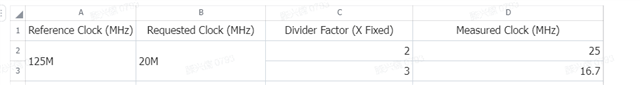
Case 1: Reference clock = 125 MHz
Device tree:
We manually modified spi-omap2-mcspi.c (omap2_mcspi_setup_transfer) and measured the clock on the oscilloscope. The calculation was:
The results show that the actual clock is always about 1/3 of the expected speed.
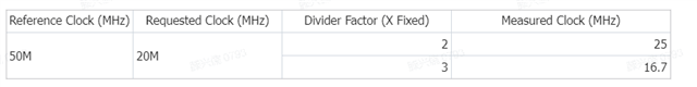
Case 2: Reference clock = 50 MHz
Device tree:
Again, we manually modified the same driver function and used the same calculation method. The oscilloscope confirmed the same mismatch issue.
Summary:
-
The SPI output clock is always about 1/3 of the requested frequency.
-
We don’t understand why any arbitrary reference clock source can be assigned and still work.
-
We want to know if 20 MHz is achievable, or if only the listed clock frequencies are supported.
Could you please help clarify how SPI clock generation works on TDA4 and whether our observations are expected behavior?
Thanks a lot.