This thread has been locked.

If you have a related question, please click the "Ask a related question" button in the top right corner. The newly created question will be automatically linked to this question.

AM62A7: AM62A7 power TIMING

Part Number: AM62A7
Other Parts Discussed in Thread: TPS65224

Tool/software:

Hello, engineers 

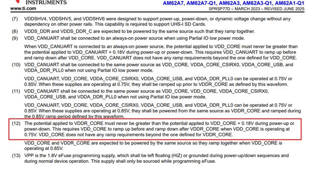
When I was testing the power-down sequence of AM62A7, I found that the manual has such a requirement: VDDR_CORE (0V85) needs to be always less than VDD_CORE (0V75) + 0.18V during the power-down process. That is, during the power-down process, I need to ensure that VDDR_CORE is powered off first before powering off VDD_CORE. Or, during the entire power-down process, the power-off rate of VDDR_CORE should be faster than that of VDD_CORE. Without additional discharge circuits, this is very difficult because the power-down time of the power supply is strongly related to the capacitance value of the attached capacitor.
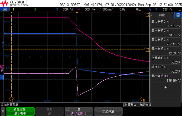
The following waveform is the actual measurement of the power-down timing sequence I conducted using the PMIC TPS65224. The red line represents VDDR_CORE, the blue line represents VDD_CORE, and the purple line represents the difference between VDD_CORE and VDDR_CORE. This subtraction value needs to always be greater than -0.18V. From the test waveform, it can be seen that this clearly does not meet the requirement; however, it can be confirmed that the power-down timing sequence can satisfy that the enable of VDDR_CORE is pulled down first, and then the enable of VDD_CORE is pulled down; and VDD_CORE is sourced from the BUCK circuit, while VDDR_CORE is sourced from the LDO circuit. The power-down rate of VDD_CORE is very fast.
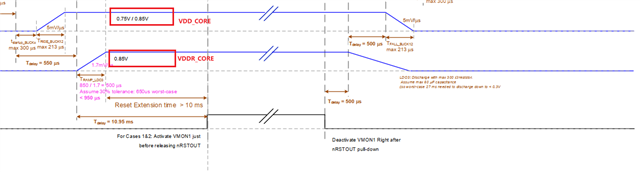
The following is the OTP timing diagram of TPS65224 combined with AM62A7. It can be seen that the power-down timing of OTP also fails to meet the required timing specified in the AM62A7 manual.
My questions are as follows:

1.During the power-on phase, meeting this requirement is quite easy. However, during the power-off phase, I wonder why it is necessary for VDDR_CORE to be completely powered off earlier than VDD_CORE, because these two actually can share the same power supply 0V85.

2.Based on my current power supply design, this requirement cannot be met. What impact will it have on my system? Do I need to modify the circuit to meet the timing requirements at this time?

Thank you for your help.

Xiwen

  • Hi Xiwen,

    The sequence requirements between VDD_CORE and VDDR_CORE must be followed during the power-up sequence. This is a hard requirement. 

    For power down, we strongly recommend to discharge VDDR_CORE below ~300mV before turning-OFF the next rail in sequence (VDD_CORE). However, we don't have any data that would indicate an issue if VDD_CORE discharges faster than VDDR_CORE during power-down. This power-down requirement is included in the spec because having a potential on VDDR_CORE greater than VDD_CORE + 0.18V during power-down is not fully validated/characterized. 

    Thanks,

    Brenda

  • Hi,Brenda

    Thank you. I will attempt to modify the discharge path of the VDDR_CORE power supply to accelerate the power-down speed. I would like to know if there is a down-power sequence requirement for the VDD_CORE and VDDR_CORE voltages that can ensure the safety of the SOC. For example, you mentioned a voltage below 300mV. We will try to achieve this goal to ensure the system's safety.

  • There are no additional sequence requirements beyond the ones specified in the datasheet. The ~300mV recommended discharge threshold is applicable to all SoC rails during power-down.

    It is recommended to discharge a supply group below ~300mV before the next rail in sequence is turned OFF.  

    Thanks,

    Brenda

  • Hi,Brenda

    We enabled the 200Ω discharge path of PMIC(TPS65224) LDO3. However, the power-off test still failed to meet this requirement(It is recommended to discharge a supply group below ~300mV before the next rail in sequence is turned OFF.)

    The discharge speed of BUCK_CORE is much faster than that of LDO3. 

    The power-on/off timing OTP of this PMIC is specifically designed by TI for use with AM62A7. We are unable to modify the OTP of the PMIC. Does your team have a better power solution to offer? Or are there any other ways of design optimization?

    The attachment contains the EVM design.AM62P_BURTON_EVM_CONCEPT.pdf

    Thanks,

    Xiwen

  • Hi Xiwen,

    To optimize the design even further, you could consider al logic implementation like the example below to add external discharge resistor to the rail that is discharging slow. It is strongly recommended to simulate any logic implementation before implementation. 

    Thanks,

    Brenda

  • Hi,Brenda

    I also want to know what impact this would have on my system if the power-down sequence of my system, VDDR_CORE and VDD_CORE fail to meet the aforementioned requirements. Have your team ever encountered such issues? I have completed the electrical testing of all signals of the SOC. Currently, only this one does not meet the requirements specified in the manual. If I conduct further investigation experiments and the SOC does not have any problems in the environmental, electrical performance, and EMC tests, can this prove the stability of the system?

    Thanks,

    Xiwen

  • Hi Xiwen,

    We don't have any data that would indicate an issue if VDD_CORE discharges faster than VDDR_CORE during power-down.

    Thanks,

    Brenda