Part Number: AM3352
Tool/software:
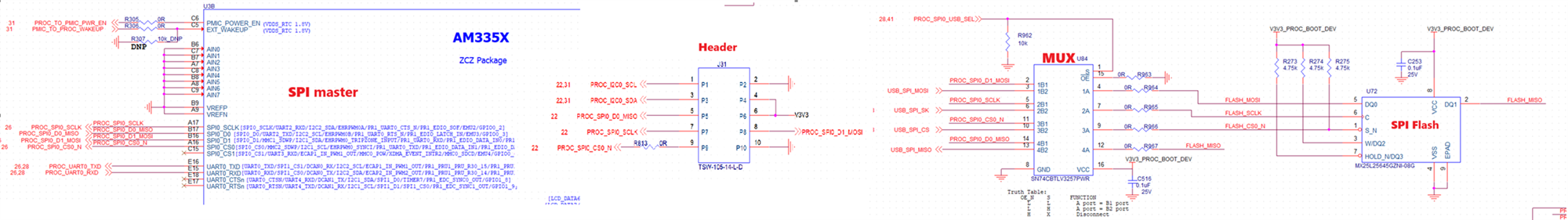
Schematic: Master is PROC AM3352 U3, the SPI0_CLK goes from PROC to the MUX U84 . The output of the MUX goes to the SPI slave U72. There is also a header J31 on this SPI0 bus for measurement. On PCB, the trace goes from U3->J31->U84.
Problem statement: A few boards failed bootup. It always stuck at "Starting kernel..". We made several experiments on this boards:
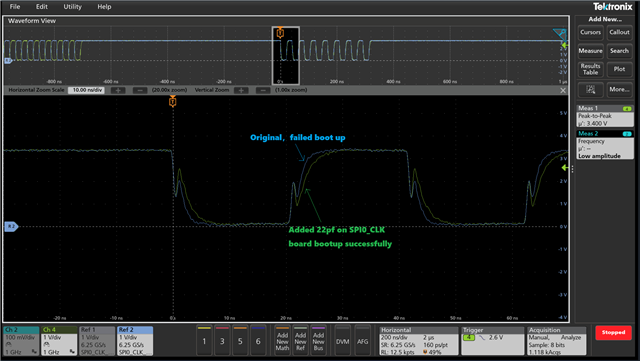
a. Adding 3.6pF capacitor on PROC_SPI0_CLK can make the board boot up successfully.
b. Add 1K PD resistors on PROC_SPI0_CLK, it also work
c. Cut off PROC_SPI0_CLK. then insert a 22ohm series resistor, it makes the board boot up successfully.
At the beginning, we suspect if there is big overshoot on PROC_SPI0_CLK, so we measured this net on the destination(U84.5 pin), the waveform is perfect, no overshoot, no undershoot. See the waveform below.
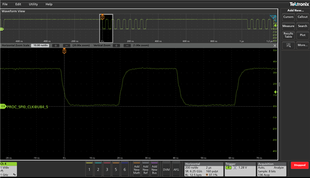
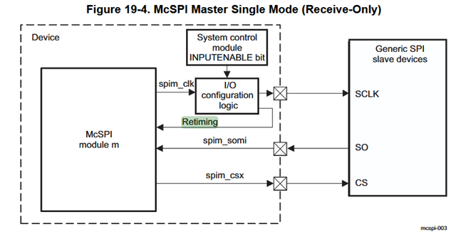
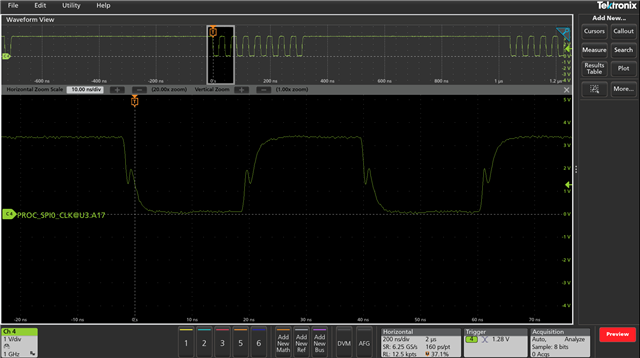
How does PROC (master) side samples the MISO signal? Is it sampled by the SPI0_CLK on PROC’s pin or is it sampled by PROC internal clock before the output flip-flop? Can you please help to share the internal block diagram for SPI0_CLK. We measured PROC_SPI0_CLK on the source side(AM3352 A17 pin). There is ditch on the rising and falling edge of SPI0_CLK. If the MISO is sampled on the SPI0_CLK on the output pin, the ditch may cause problem.
We are trying to understand the root cause for this issue. Very appreciate if you can help us.