


Tool/software:
Our team is currently debugging the CAN function and has encountered a problem where data can be sent out normally but cannot be received properly. Below is a detailed description of the project.
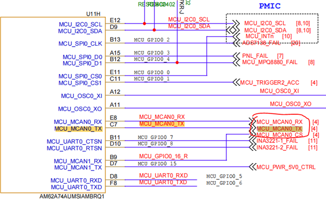
The main control chip uses AM62A74AUMSIAMBRQ1, and the CAN transceiver uses SIT1044QT. The pins used are MCU_SCAN0-RX (E8), MCU_SCAN0_TX (C7), and MCU_SPIO0_16 (B9). The hardware schematic is as follows:
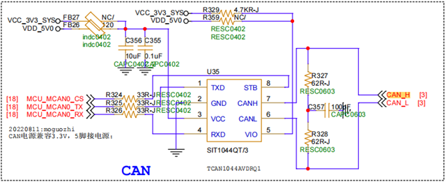
According to the data manual of SIT1044QT, when the STB is at high level, it is in standby mode, and when the STB is at low level, it is in working mode.
SDK version: 10.00.00.08

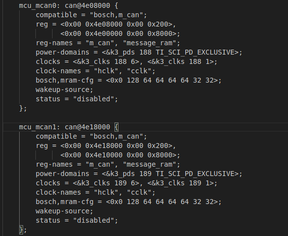
Therefore, the configuration of the device tree file is as follows: k3-am62a7-sk.dts (this is the content I added)
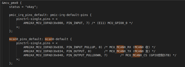
And the relevant files are using the SDK's built-in k3-am62a-mcu.dtsi (the file content has not been modified, and the configuration is as follows)
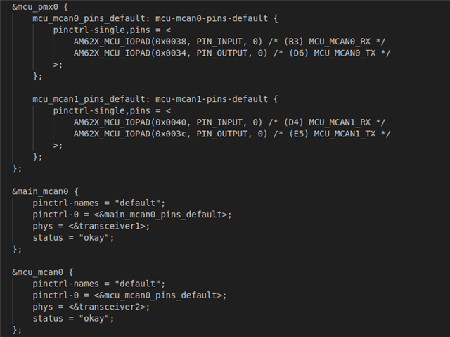
I have learned that k3-am62x-sk-mcan.dtso will dynamically overwrite some configurations of k3-am62a7-sk.dts, so currently regarding pin control instructions, I will still control them again through user space. To ensure that the pins are set to the shape I want.
Here, the content of k3-am62x-sk-mcan.dtso is also presented as a reference. I haven't made any changes to the content of this file either.
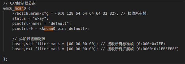
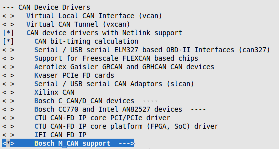
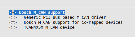
Here is the driver configuration. I configured it based on the documentation
Then I added some debugging prints to the various functions in the m_can. c file. Debug on the board end through instructions. Connect a CAN simulator to the TI development board for communication testing. Here are my debugging instructions and the printing situation at each stage
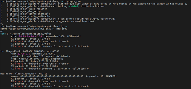
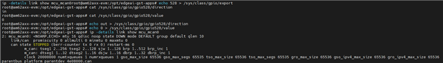
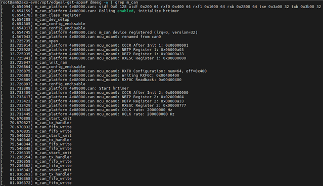
Check the CAN initialization status when the board is first powered on
Input:dmesg -w | grep m_can
Display:
[ 0.644923] m_can_platform 4e08000.can: sidf 0x0 128 xidf 0x200 64 rxf0 0x400 64 rxf1 0x1600 64 rxb 0x2800 64 txe 0x3a00 32 txb 0x3b00 32
[ 0.644982] m_can_platform 4e08000.can: Polling enabled, initialize hrtimer
[ 0.645001] m_can_class_register
[ 0.645109] m_can_dev_setup
[ 0.645124] m_can_config_endisable
[ 0.645135] m_can_config_endisable
[ 0.645527] m_can_platform 4e08000.can: m_can device registered (irq=0, version=32)
[ 4.451022] m_can_platform 4e08000.can mcu_mcan0: renamed from can0
Input:ifconfig -a
Display:
eth0: flags=4099<UP,BROADCAST,MULTICAST> mtu 1500
on
echo 0 > /sys/class/gpio/gpio528/value
ether 98:03:8a:80:a2:39 txqueuelen 1000 (Ethernet)
RX packets 0 bytes 0 (0.0 B)
RX errors 0 dropped 0 overruns 0 frame 0
TX packets 0 bytes 0 (0.0 B)
TX errors 0 dropped 0 overruns 0 carrier 0 collisions 0
lo: flags=73<UP,LOOPBACK,RUNNING> mtu 65536
inet 127.0.0.1 netmask 255.0.0.0
inet6 ::1 prefixlen 128 scopeid 0x10<host>
loop txqueuelen 1000 (Local Loopback)
RX packets 19 bytes 2253 (2.2 KiB)
RX errors 0 dropped 0 overruns 0 frame 0
TX packets 19 bytes 2253 (2.2 KiB)
TX errors 0 dropped 0 overruns 0 carrier 0 collisions 0
mcu_mcan0: flags=128<NOARP> mtu 16
unspec 00-00-00-00-00-00-00-00-00-00-00-00-00-00-00-00 txqueuelen 10 (UNSPEC)
RX packets 0 bytes 0 (0.0 B)
RX errors 0 dropped 0 overruns 0 frame 0
TX packets 0 bytes 0 (0.0 B)
TX errors 0 dropped 0 overruns 0 carrier 0 collisions 0
Pull down the STB pin of the CAN transceiver to enable it to function properly
Input:
echo 528 > /sys/class/gpio/export
cat /sys/class/gpio/gpio528/direction
cat /sys/class/gpio/gpio528/value
echo out > /sys/class/gpio/gpio528/direction
echo 0 > /sys/class/gpio/gpio528/value
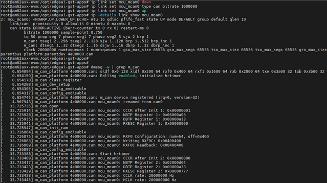
ip -details link show mcu_mcan0
Display:
2: mcu_mcan0: <NOARP,ECHO> mtu 16 qdisc noop state DOWN mode DEFAULT group default qlen 10
link/can promiscuity 0 allmulti 0 minmtu 0 maxmtu 0
can state STOPPED (berr-counter tx 0 rx 0) restart-ms 0
m_can: tseg1 2..256 tseg2 2..128 sjw 1..128 brp 1..512 brp_inc 1
m_can: dtseg1 1..32 dtseg2 1..16 dsjw 1..16 dbrp 1..32 dbrp_inc 1
clock 20000000 numtxqueues 1 numrxqueues 1 gso_max_size 65536 gso_max_segs 65535 tso_max_size 65536 tso_max_segs 65535 gro_max_size 65536 gso_ipv4_max_size 65536 gro_ipv4_max_size 65536 parentbus platform parentdev 4e08000.can
Then pull up the CAN
Input:
ip link set mcu_mcan0 down
ip link set mcu_mcan0 type can bitrate 1000000
ip link set mcu_mcan0 up
ip -details link show mcu_mcan0
dmesg -w | grep m_can
Display:
ip -details link show mcu_mcan0
2: mcu_mcan0: <NOARP,UP,LOWER_UP,ECHO> mtu 16 qdisc pfifo_fast state UP mode DEFAULT group default qlen 10
link/can promiscuity 0 allmulti 0 minmtu 0 maxmtu 0
can state ERROR-ACTIVE (berr-counter tx 0 rx 0) restart-ms 0
bitrate 1000000 sample-point 0.750
tq 50 prop-seg 7 phase-seg1 7 phase-seg2 5 sjw 2 brp 1
m_can: tseg1 2..256 tseg2 2..128 sjw 1..128 brp 1..512 brp_inc 1
m_can: dtseg1 1..32 dtseg2 1..16 dsjw 1..16 dbrp 1..32 dbrp_inc 1
clock 20000000 numtxqueues 1 numrxqueues 1 gso_max_size 65536 gso_max_segs 65535 tso_max_size 65536 tso_max_segs 65535 gro_max_size 65536 gso_ipv4_max_size 65536 gro_ipv4_max_size 65536 parentbus platform parentdev 4e08000.can
dmesg -w | grep m_can
[ 0.654094] m_can_platform 4e08000.can: sidf 0x0 128 xidf 0x200 64 rxf0 0x400 64 rxf1 0x1600 64 rxb 0x2800 64 txe 0x3a00 32 txb 0x3b00 32
[ 0.654159] m_can_platform 4e08000.can: Polling enabled, initialize hrtimer
[ 0.654178] m_can_class_register
[ 0.654288] m_can_dev_setup
[ 0.654305] m_can_config_endisable
[ 0.654317] m_can_config_endisable
[ 0.654745] m_can_platform 4e08000.can: m_can device registered (irq=0, version=32)
[ 4.567943] m_can_platform 4e08000.can mcu_mcan0: renamed from can0
[ 33.725735] m_can_open
[ 33.725914] m_can_platform 4e08000.can mcu_mcan0: CCCR After Init 1: 0x00000001
[ 33.725928] m_can_platform 4e08000.can mcu_mcan0: NBTP Register 1: 0x06000a03
[ 33.725935] m_can_platform 4e08000.can mcu_mcan0: DBTP Register 1: 0x00000a33
[ 33.725941] m_can_platform 4e08000.can mcu_mcan0: RXESC Register 1: 0x00000000
[ 33.725947] m_can_init_ram
[ 33.726864] m_can_config_endisable
[ 33.726875] m_can_platform 4e08000.can mcu_mcan0: RXF0 Configuration: num=64, off=0x400
[ 33.726883] m_can_platform 4e08000.can mcu_mcan0: Writing RXF0C: 0x00400400
[ 33.726889] m_can_platform 4e08000.can mcu_mcan0: RXF0C Readback: 0x00400400
[ 33.726897] m_can_config_endisable
[ 33.733388] m_can_platform 4e08000.can: Start hrtimer
[ 33.733409] m_can_platform 4e08000.can mcu_mcan0: CCCR After Init 2: 0x00000000
[ 33.733417] m_can_platform 4e08000.can mcu_mcan0: NBTP Register 2: 0x02000d04
[ 33.733423] m_can_platform 4e08000.can mcu_mcan0: DBTP Register 2: 0x00000a33
[ 33.733429] m_can_platform 4e08000.can mcu_mcan0: RXESC Register 2: 0x00000777
[ 33.733438] m_can_platform 4e08000.can mcu_mcan0: CCLK rate: 20000000 Hz
[ 33.733445] m_can_platform 4e08000.can mcu_mcan0: HCLK rate: 200000000 Hz
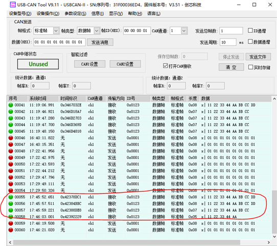
Sending CAN data to CAN simulator on TI development board
Input:
cansend mcu_mcan0 123#11223344AABBCCDD
cansend mcu_mcan0 123#11223344AABBCCDD
cansend mcu_mcan0 123#11223344AABBCC
cansend mcu_mcan0 123#11223344AA
Display successful data reception on the upper computer of the CAN simulator
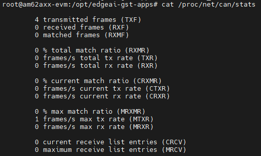
At this point, the board end is printed as:
cat /proc/net/can/stats
4 transmitted frames (TXF)
0 received frames (RXF)
0 matched frames (RXMF)
0 % total match ratio (RXMR)
0 frames/s total tx rate (TXR)
0 frames/s total rx rate (RXR)
0 % current match ratio (CRXMR)
0 frames/s current tx rate (CTXR)
0 frames/s current rx rate (CRXR)
0 % max match ratio (MRXMR)
1 frames/s max tx rate (MTXR)
0 frames/s max rx rate (MRXR)
0 current receive list entries (CRCV)
0 maximum receive list entries (MRCV)
dmesg -w | grep m_can
[ 0.654094] m_can_platform 4e08000.can: sidf 0x0 128 xidf 0x200 64 rxf0 0x400 64 rxf1 0x1600 64 rxb 0x2800 64 txe 0x3a00 32 txb 0x3b00 32
[ 0.654159] m_can_platform 4e08000.can: Polling enabled, initialize hrtimer
[ 0.654178] m_can_class_register
[ 0.654288] m_can_dev_setup
[ 0.654305] m_can_config_endisable
[ 0.654317] m_can_config_endisable
[ 0.654745] m_can_platform 4e08000.can: m_can device registered (irq=0, version=32)
[ 4.567943] m_can_platform 4e08000.can mcu_mcan0: renamed from can0
[ 33.725735] m_can_open
[ 33.725914] m_can_platform 4e08000.can mcu_mcan0: CCCR After Init 1: 0x00000001
[ 33.725928] m_can_platform 4e08000.can mcu_mcan0: NBTP Register 1: 0x06000a03
[ 33.725935] m_can_platform 4e08000.can mcu_mcan0: DBTP Register 1: 0x00000a33
[ 33.725941] m_can_platform 4e08000.can mcu_mcan0: RXESC Register 1: 0x00000000
[ 33.725947] m_can_init_ram
[ 33.726864] m_can_config_endisable
[ 33.726875] m_can_platform 4e08000.can mcu_mcan0: RXF0 Configuration: num=64, off=0x400
[ 33.726883] m_can_platform 4e08000.can mcu_mcan0: Writing RXF0C: 0x00400400
[ 33.726889] m_can_platform 4e08000.can mcu_mcan0: RXF0C Readback: 0x00400400
[ 33.726897] m_can_config_endisable
[ 33.733388] m_can_platform 4e08000.can: Start hrtimer
[ 33.733409] m_can_platform 4e08000.can mcu_mcan0: CCCR After Init 2: 0x00000000
[ 33.733417] m_can_platform 4e08000.can mcu_mcan0: NBTP Register 2: 0x02000d04
[ 33.733423] m_can_platform 4e08000.can mcu_mcan0: DBTP Register 2: 0x00000a33
[ 33.733429] m_can_platform 4e08000.can mcu_mcan0: RXESC Register 2: 0x00000777
[ 33.733438] m_can_platform 4e08000.can mcu_mcan0: CCLK rate: 20000000 Hz
[ 33.733445] m_can_platform 4e08000.can mcu_mcan0: HCLK rate: 200000000 Hz
[ 70.670808] m_can_start_xmit
[ 70.670827] m_can_tx_handler
[ 70.670832] m_can_fifo_write
[ 70.670835] m_can_fifo_write
[ 75.540322] m_can_start_xmit
[ 75.540340] m_can_tx_handler
[ 75.540344] m_can_fifo_write
[ 75.540348] m_can_fifo_write
[ 77.236335] m_can_start_xmit
[ 77.236354] m_can_tx_handler
[ 77.236358] m_can_fifo_write
[ 77.236362] m_can_fifo_write
[ 81.036342] m_can_start_xmit
[ 81.036363] m_can_tx_handler
[ 81.036368] m_can_fifo_write
[ 81.036372] m_can_fifo_write
On the upper computer of the CAN simulator, data was sent to the TI development board, but the TI development board did not display the received data.
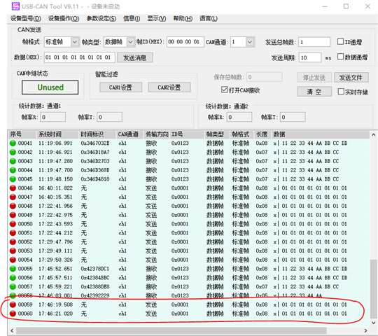
Input: candump - t d - e mcu_can0
No data displayed
Input: dmesg - w | grep m_can
Display (actually printing when TI development board sends data, without any additional printing)
[ 0.654094] m_can_platform 4e08000.can: sidf 0x0 128 xidf 0x200 64 rxf0 0x400 64 rxf1 0x1600 64 rxb 0x2800 64 txe 0x3a00 32 txb 0x3b00 32
[ 0.654159] m_can_platform 4e08000.can: Polling enabled, initialize hrtimer
[ 0.654178] m_can_class_register
[ 0.654288] m_can_dev_setup
[ 0.654305] m_can_config_endisable
[ 0.654317] m_can_config_endisable
[ 0.654745] m_can_platform 4e08000.can: m_can device registered (irq=0, version=32)
[ 4.567943] m_can_platform 4e08000.can mcu_mcan0: renamed from can0
[ 33.725735] m_can_open
[ 33.725914] m_can_platform 4e08000.can mcu_mcan0: CCCR After Init 1: 0x00000001
[ 33.725928] m_can_platform 4e08000.can mcu_mcan0: NBTP Register 1: 0x06000a03
[ 33.725935] m_can_platform 4e08000.can mcu_mcan0: DBTP Register 1: 0x00000a33
[ 33.725941] m_can_platform 4e08000.can mcu_mcan0: RXESC Register 1: 0x00000000
[ 33.725947] m_can_init_ram
[ 33.726864] m_can_config_endisable
[ 33.726875] m_can_platform 4e08000.can mcu_mcan0: RXF0 Configuration: num=64, off=0x400
[ 33.726883] m_can_platform 4e08000.can mcu_mcan0: Writing RXF0C: 0x00400400
[ 33.726889] m_can_platform 4e08000.can mcu_mcan0: RXF0C Readback: 0x00400400
[ 33.726897] m_can_config_endisable
[ 33.733388] m_can_platform 4e08000.can: Start hrtimer
[ 33.733409] m_can_platform 4e08000.can mcu_mcan0: CCCR After Init 2: 0x00000000
[ 33.733417] m_can_platform 4e08000.can mcu_mcan0: NBTP Register 2: 0x02000d04
[ 33.733423] m_can_platform 4e08000.can mcu_mcan0: DBTP Register 2: 0x00000a33
[ 33.733429] m_can_platform 4e08000.can mcu_mcan0: RXESC Register 2: 0x00000777
[ 33.733438] m_can_platform 4e08000.can mcu_mcan0: CCLK rate: 20000000 Hz
[ 33.733445] m_can_platform 4e08000.can mcu_mcan0: HCLK rate: 200000000 Hz
[ 70.670808] m_can_start_xmit
[ 70.670827] m_can_tx_handler
[ 70.670832] m_can_fifo_write
[ 70.670835] m_can_fifo_write
[ 75.540322] m_can_start_xmit
[ 75.540340] m_can_tx_handler
[ 75.540344] m_can_fifo_write
[ 75.540348] m_can_fifo_write
[ 77.236335] m_can_start_xmit
[ 77.236354] m_can_tx_handler
[ 77.236358] m_can_fifo_write
[ 77.236362] m_can_fifo_write
[ 81.036342] m_can_start_xmit
[ 81.036363] m_can_tx_handler
[ 81.036368] m_can_fifo_write
[ 81.036372] m_can_fifo_write
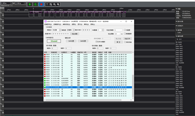
But I used a logic analyzer to measure and found that the data sent by the CAN simulator to the TI development board was normal before reaching the CAN transceiver. So it seems that there is not a problem with the data itself, but rather a loss caused by problems during the processing stage?
The baud rate is set to 1M. Then the CAN simulator sends data to the TI development board, and the logic analyzer can correctly capture the data (the logic analyzer is connected to the CAN_S and CAN_L wires)
So, regarding the current issue of TI development boards being able to send data but unable to receive data properly, I would like to inquire about the cause of the problem and how I can solve it.
