

Other Parts Discussed in Thread: SYSCONFIG, TDA4VH-Q1
Tool/software:
What is the K3 Resource Partitioning tool? What is it useful for within my application? How do I use it?

The K3 Resource Partitioning tool is a SysConfig based tool used to allocate specific system level resources to the various cores of the TDA4 multi-core SoCs. The main and most common use case is partitioning resources such as DMA channels, NAVSS rings, proxies, interrupts, and more. You can find all details on getting started, setting up, and more documentation within the Linux SDK docs. Please follow the 'Getting Started' instructions from the Linux SDK docs FIRST before continuing. Another option is to use the online SysConfig tool with the following configuration for 'Resource partitioning tool for Multi-Core SoCs (1.0.0)' and your device:

Image 1: Online SysConfig tool
The K3 Resource Partitioning tool is a way to manipulate the default resource allocations. Within the RTOS PDK, the standard board config that is packaged and compiled by default is found at [RTOS_SDK_PATH]/PDK/packages/ti/drv/sciclient/soc/V6/sciclient_defaultBoardcfg_rm.c. This file demonstrates the default resources allocated within the standard SDK and can be manipulated and customized to fit your application or use case. You can utilize this as the starting point by selecting the 'Latest Baseline Design' from Image 1 if you are using the online SysConfig tool. The steps are very similar if you are using the SysConfig tool locally with Linux SDK 11.1+. However, if you are using Linux SDK 11.0 or before, you will have to load the baseline default config by selecting 'Browse' as shown in Image 2 and navigating to [LINUX_INSTALL_PATH]/board_support/k3-respart-tool/out/[DEVICE].syscfg. You can also start from scratch, however, we do not recommend this.
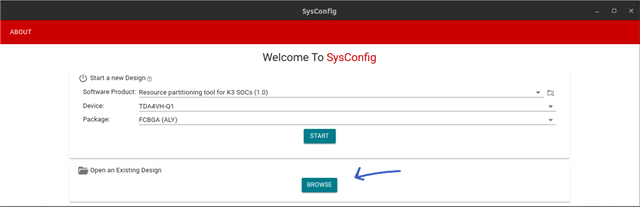
Image 2: Browse to load baseline default config, for ex. ti-processor-sdk-linux-adas-j784s4-evm-11_01_00_03/board-support/k3-respart-tool/out/j784s4-evm.syscfg
This tool would be very useful in a variety of scenarios. For example, if our application requires 2 WKUP_GPIO interrupts on MCU3_0 using TDA4VH-Q1, here are the steps we would take to enable this.
First, we have to check how many interrupt lines MCU3_0 has allocated for the WKUP GPIO Interrupt Router. We can see this information by navigating to the MAIN_1_R5_0 core on the left and viewing the 'Wakeup GPIO Interrupt router Count'. Image 3 shows in the default board configuration, there are 0 interrupt lines allocated for MAIN_1_R5_0 or MCU3_0 for J784S4 device. Due to this, we will have to allocate 2 interrupt lines to MCU3_0 core.

Image 3: WKUP GPIO Interrupt Router allocations for MAIN_1_R5_0
Additionally, the Resource Allocation Table, on the right of Image 3, makes it very simple to see the complete WKUP GPIO Interrupt Router allocations for all the cores. Refer to Image 4 on how to enable this.
Default WKUP GPIO Interrupt Router Allocations for all cores:
| A72_2 | A72_3 | C7X_0_1 | C7X_1_1 | C7X_2_1 | C7X_3_1 | MAIN_0_R5_0 | MAIN_0_R5_2 | MAIN_1_R5_0 | MAIN_1_R5_2 | MAIN_2_R5_0 | MAIN_2_R5_2 | MCU_0_R5_0 | MCU_0_R5_2 | |
|---|---|---|---|---|---|---|---|---|---|---|---|---|---|---|
| Count | 6 | 6 | 0 | 0 | 0 | 0 | 2 | 2 | 0 | 0 | 0 | 0 | 8 | 8 |

Image 4: How to view Resource Allocation Table in SysConfig
Since there are 0 interrupt lines, we must move and reallocate 2 lines from another core to MCU 3_0. However, we will not be able to allocate 2 lines until we free resources from another core, and the tool will throw an error if we try as shown in Image 5. We can move resources from MAIN_0_R5_2 by changing the count for WKUP GPIO Interrupt router to 0, then we will be able to go back to the MAIN_1_R5_0 core and set the count to 2 as shown in Image 6. We will be able to see the changes reflected in the Allocation Table on the right of Image 6 where we can see the 2 interrupt lines which previously were allocated for MAIN_0_R5_2 in Image 3 are now under MAIN_1_R5_0 as we need.

Image 5: Lack of resources causes an error and must be reallocated

Image 6: Updated resource allocation interrupt lines for MCU3_0
For devices J721S2 and J784S4, we recommend using the Appendix Excel file packaged within the Technical Reference Manual for details of interrupt sources and destinations for any instance. What you see in the appendix (J721S2_Appendix_20241106_Public.xlsx), which is shown in Image 7, is the total number of interrupt lines routed from the WKUP GPIO Interrupt Router to the Main R50_0 core. However, these are muxed in software to make room for other interrupts to the core as the core only has a certain number of interrupt lines. The specific interrupt lines that are enabled and muxed are configured by the board resource manager or RM. For example in Image 7, although WKUP_GPIOMUX_INTRTR_OUTP_OUT_[16:31] are connected and routed to R5FSS1_CORE0_INTR_IN_[488:503], that does not mean you can configure interrupts on all these lines unless it is specified in the board rm config. The default board rm config specifies 0 interrupt lines, however, we can now generate 2 interrupts with the changes we made.
From the right side of Image 6, hovering over the Allocation Table we can also see the start and count for the interrupt lines. This can also be read by parsing the sciclient_defaultBoardcfg_rm.c file for RTOS. Based on these values, we know interrupt IDs 30 and 31 for WKUP GPIO Interrupt router is allocated to the MCU3_0 core. Cross-referencing this with the screenshot from the appendix as shown below, we can see the destination interrupt numbers at the MCU3_0 core will be 502 and 503.

Image 7: Appendix: Total interrupt lines routed from WKUP_GPIOMUX_INTRTR to R5FSS1_CORE0
Now that we have made the adjustments you need, we recommend saving the .syscfg file after making any resource allocation adjustments to keep track of your changes by going to File > Save As at the top left. This will allow you to save your customized *.syscfg file. This way if you need to make minor tweaks in the future, you do not need to start from scratch or from the default board cfg. You can simply start editing from your customized allocations by going to File > Open at the top left and navigating to your saved *.syscfg file.
Finally, after you have manipulated the resource allocations as you wish depending on your specific use case and application, the tool will generate different output files. These output files will be specifically generated based on your allocations and have the RM board config data for the Linux and RTOS SDK to compile. The last and final step is to rebuild with the generated files to integrate your RM changes into the bootloader.
The following is an outline of the generated files:
RTOS SDK (PDK)
|
Filename |
Used by |
Output destination |
Comments |
|---|---|---|---|
|
sciclient_defaultBoardcfg.c |
PDK Sciclient |
[PDK_PATH]/packages/ti/drv/sciclient/soc/V<X>/ |
e.g. - pdk/packages/ti/drv/sciclient/soc/V1/sciclient_defaultBoardcfg.c |
|
sciclient_defaultBoardcfg_rm.c |
PDK Sciclient |
[PDK_PATH]/packages/ti/drv/sciclient/soc/V<X>/ |
e.g. - pdk/packages/ti/drv/sciclient/soc/V1/sciclient_defaultBoardcfg_rm.c |
|
sciclient_defaultBoardcfg_tifs_rm.c |
PDK Sciclient |
[PDK_PATH]/packages/ti/drv/sciclient/soc/V<X>/ |
e.g. - pdk/packages/ti/drv/sciclient/soc/V1/sciclient_defaultBoardcfg_tifs_rm.c |
Value of <X> for each device:
RTOS SDK (MCU+ SDK for J722S)
|
Filename |
Used by |
Output destination |
Comments |
|---|---|---|---|
|
sciclient_defaultBoardcfg.c |
MCU+ SDK Sciclient |
[MCU+SDK_PATH]/source/drivers/sciclient/sciclient_default_boardcfg/j722s/ |
e.g. - mcu_plus_sdk_j722s/source/drivers/sciclient/sciclient_default_boardcfg/j722s/sciclient_defaultBoardcfg.c |
|
sciclient_defaultBoardcfg_rm.c |
MCU+ SDK Sciclient |
[MCU+SDK_PATH]/source/drivers/sciclient/sciclient_default_boardcfg/j722s/ |
e.g. - mcu_plus_sdk_j722s/source/drivers/sciclient/sciclient_default_boardcfg/j722s/sciclient_defaultBoardcfg_rm.c |
Linux SDK 9.0+
|
Filename |
Used by |
Output destination |
Comments |
|---|---|---|---|
| rm-cfg.yaml |
U-boot |
[LINUX_SDK_PATH]/board-support/u-boot-<XYZ>/board/ti/<soc>/ | e.g. -u-boot/board/ti/j784s4/rm-cfg.yaml |
| tifs-rm-cfg.yaml |
U-boot |
[LINUX_SDK_PATH]/board-support/u-boot-<XYZ>/board/ti/<soc>/ | e.g. -u-boot/board/ti/j784s4/tifs-rm-cfg.yaml |
Linux SDK 8.6 and earlier
|
Filename |
Used by |
Output destination |
Comments |
|---|---|---|---|
|
rm-cfg.c |
U-boot |
[LINUX_SDK_PATH]/board-support/k3-image-gen<X>/soc/<soc>/<profile>/ |
e.g. - k3-image-gen/soc/j784s4/evm/rm-cfg.c |
|
tifs-rm-cfg.c |
U-boot |
[LINUX_SDK_PATH]/board-support/k3-image-gen<X>/soc/<soc>/<profile>/ |
e.g. - k3-image-gen/soc/j784s4/evm/tifs-rm-cfg.c |
|
sysfw_img_cfg.h |
U-boot |
[LINUX_SDK_PATH]/board-support/k3-image-gen-<X>/soc/<soc>/<profile>/ |
e.g. - k3-image-gen/soc/j784s4/evm/sysfw_img_cfg.h |
Final Notes:
When using Linux SDK 10.0 and earlier, the Software Product 'Keystone3 Resource Partitioning Tool (0.5)' has a known bug in the generated rm-cfg.yaml file with some indentations and spacing. This bug and issue in the file generated by SysConfig causes issues when trying to build your rm changes into U-boot. The fix has now been implemented and continue to use Software Product 'Resource partitioning tool for Multi-Core SoCs (1.0.0)' for further development with the correct generated file rm-cfg.yaml file.
