AM6442: Bidirectional GPIO Loopback Testing Without Device Tree Changes

Part Number: AM6442

Tool/software:

Hello,

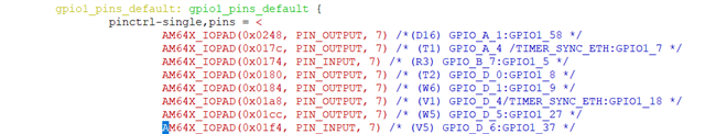
We are trying to implement a GPIO loopback between the following pins on AM64x:

GPIO1_58  and GPIO1_37 

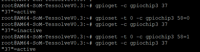
With this configuration, the loopback works in one direction — writing to GPIO1_58 and reading from GPIO1_37 works correctly.

However, when we try the reverse — writing to GPIO1_37 and reading from GPIO1_58 — it doesn't work.

How can we test bidirectional GPIO loopback without having to modify the Device Tree each time?

Here are the screenshots for the above mentioned cases:

Writing to the output pin GPIO1_58 and reading through the GPIO1_37 is successful.


But the other way loopback where writing to GPIO1_37 and reading from the GPIO1_58 is not working as expected.


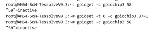
Could you please suggest what might be causing this issue?

  • Hello Anjana Rao,

    Do you change the configuration of the pins in the second case - setting GPIO1_37 as output (in your pin initialization routine) vs GPIO1_58 as input (in the devtree dtsi). I am asking because you do not have a screenshot of the changed dtsi configuration corresponding to your second testcase.

    How can we test bidirectional GPIO loopback without having to modify the Device Tree each time?

    To avoid modifying the device tree each time, I would propose that:

    1. Within the same dtsi "static" configuration, you also enable the input LVCMOS buffer of the GPIO1_58 corresponding pin.

    You can try replacing your GPIO_A_1:GPIO1_58 line with the following line:

    gpio1_pins_default: gpio1-pins-default {
    pinctrl-single,pins = <

    AM64X_IOPAD(0x0248, PIN_INPUT, 7) /* (D16) UART1_CTSn.GPIO1_58 */

    .........................................

    2 .Then comes the question regarding GPIO1_37 and GPO1_58 output buffers control which is NOT part of the device tree, because of the need of run-time control over the pins output buffer. I am not a Linux expert, so I would describe it from a low level (hardware) perspective:

    2.1. Initially disable GPIO1_37 and GPIO1_58 pins output buffers in their corresponding padconf registers.

    Make sure that you are aware which GPIO user space command (or program routine) will disable / enable a pin output buffer, to appropriately follow the below sequencies.

    2.2. Setup the Muxmodes of the two pins accordingly.

    2.3A When GPIO1_37 shall transmit to GPIO1_58:

    First set the GPIO1_58 & GPIO1_37 output buffers disabled (to avoid output vs output contention), then set GPIO1_37 output value and then enable the GPIO1_37 output buffer in the corresponding padconf registers.

    2.3B When GPIO1_58 shall transmit to GPIO1_37 (your first usecase)

    First set the GPIO1_37 &  GPIO1_58 output buffers disabled (to avoid output vs output contention), then set GPIO1_58 output value and then enable the GPIO1_58 output buffer in the corresponding padconf registers.

    This will result in need to change control of the GPIO1_37  and GPIO1_58 output buffers in your program / terminal session when you flip the direction, but always use the same devtree dtsi configuration.   


    Please make sure that your code takes care to synchronize outputs enabling/disabling via some "direction change" protocol.

    Thanks

    Kind Regards,

    Anastas Yordanov