AM62A7: Hot enable DPI display on AM62A7

Part Number: AM62A7
Other Parts Discussed in Thread: SYSCONFIG

Tool/software:

Hi Ti Experts.

Following this post, I modified my device tree and compiled the application for the development board.

I logged into the system and ran kmsprint,

but nothing was output.

Here is code in my dts file about display ,Following your suggested test code

	panel {
			compatible = "newhaven,nhd-4.3-480272ef-atxl";

			port {
					panel_in: endpoint {
							remote-endpoint = <&dpi1_out>;
					};
			};
	};
	
	
&dss_ports {
	/* VP2: DPI Output */
	hdmi0_dss: port@1 {
		reg = <1>;

		dpi1_out: endpoint {

			remote-endpoint = <&panel_in>;
		};
	};
};

I noticed some errors.

[ 0.440458] /bus@f0000/dss@30200000: Fixed dependency cycle(s) with /panel
[ 0.447554] /panel: Fixed dependency cycle(s) with /bus@f0000/dss@30200000

[ 0.821931] panel-simple panel: supply power not found, using dummy regulator

  • Hi,
    Please share your complete dts and also try running kmstest to check if you see anything on panel.
    Also, what do you mean by 'hot enable DPI'?

  • // SPDX-License-Identifier: GPL-2.0-only OR MIT
    /*
     * AM62A SK: https://www.ti.com/lit/zip/sprr459
     *
     * Copyright (C) 2022-2024 Texas Instruments Incorporated - https://www.ti.com/
     */
    
    /dts-v1/;
    
    #include <dt-bindings/leds/common.h>
    #include <dt-bindings/gpio/gpio.h>
    #include <dt-bindings/net/ti-dp83867.h>
    #include "k3-am62a7.dtsi"
    
    / {
    	compatible = "ti,am62a7-sk", "ti,am62a7";
    	model = "Texas Instruments AM62A7 SK";
    
    	aliases {
    		serial0 = &wkup_uart0;
    		serial2 = &main_uart0;
    		serial5 = &main_uart5;
    		mmc0 = &sdhci0;
    		mmc1 = &sdhci1;
    		ethernet0 = &cpsw_port1;
    		spi0 = &ospi0;
    		rtc0 = &wkup_rtc0;
    		rtc1 = &tps659312;
    	};
    
    	chosen {
    		stdout-path = "serial2:115200n8";
    		bootargs = "console=ttyS2,115200n8 earlycon=ns16550a,mmio32,0x02800000 loglevel=4 root=/dev/mmcblk1p2 rw rootfstype=ext4 rootwait";
    	};
    
    	memory@80000000 {
    		device_type = "memory";
    		/* 4G RAM */
    		reg = <0x00000000 0x80000000 0x00000000 0x80000000>,
    		      <0x00000008 0x80000000 0x00000000 0x80000000>;
    	};
    
    	reserved-memory {
    		#address-cells = <2>;
    		#size-cells = <2>;
    		ranges;
    
    		/* global cma region */
    		linux,cma {
    			compatible = "shared-dma-pool";
    			reusable;
    			size = <0x00 0x24000000>;
    			alloc-ranges = <0x00 0xc0000000 0x00 0x24000000>;
    			linux,cma-default;
    		};
    
    		secure_tfa_ddr: tfa@9e780000 {
    			reg = <0x00 0x9e780000 0x00 0x80000>;
    			alignment = <0x1000>;
    			no-map;
    		};
    
    		secure_ddr: optee@9e800000 {
    			reg = <0x00 0x9e800000 0x00 0x01800000>; /* for OP-TEE */
    			alignment = <0x1000>;
    			no-map;
    		};
    
    		wkup_r5fss0_core0_dma_memory_region: r5f-dma-memory@9c800000 {
    			compatible = "shared-dma-pool";
    			reg = <0x00 0x9c800000 0x00 0x100000>;
    			no-map;
    		};
    
    		wkup_r5fss0_core0_memory_region: r5f-dma-memory@9c900000 {
    			compatible = "shared-dma-pool";
    			reg = <0x00 0x9c900000 0x00 0x01e00000>;
    			no-map;
    		};
    		mcu_r5fss0_core0_dma_memory_region: r5f-dma-memory@9b800000 {
    			compatible = "shared-dma-pool";
    			reg = <0x00 0x9b800000 0x00 0x100000>;
    			no-map;
    		};
    
    		mcu_r5fss0_core0_memory_region: r5f-dma-memory@9b900000 {
    			compatible = "shared-dma-pool";
    			reg = <0x00 0x9b900000 0x00 0x0f00000>;
    			no-map;
    		};
    
    		c7x_0_dma_memory_region: c7x-dma-memory@99800000 {
    			compatible = "shared-dma-pool";
    			reg = <0x00 0x99800000 0x00 0x100000>;
    			no-map;
    		};
    
    		c7x_0_memory_region: c7x-memory@99900000 {
    			compatible = "shared-dma-pool";
    			reg = <0x00 0x99900000 0x00 0x01f00000>;
    			no-map;
    		};
    
    		edgeai_rtos_ipc_memory_region: edgeai-rtos-ipc-memory-region {
    			reg = <0x00 0xa0000000 0x00 0x01000000>;
    			no-map;
    		};
    
    		edgeai_memory_region: edgeai-dma-memory@a1000000 {
    			compatible = "shared-dma-pool";
    			reg = <0x00 0xa1000000 0x00 0x02000000>;
    			no-map;
    		};
    
    		edgeai_shared_region: edgeai_shared-memories {
    			compatible = "dma-heap-carveout";
    			reg = <0x00 0xa3000000 0x00 0x0b000000>;
    		};
    
    		edgeai_core_heaps: edgeai-core-heap-memory@ae000000 {
    			compatible = "shared-dma-pool";
    			reg = <0x00 0xae000000 0x00 0x12000000>;
    			no-map;
    		};
    	};
    
    	opp-table {
    		/* Add 1.4GHz OPP for am62p5-sk board. Requires VDD_CORE at 0v85 */
    		opp-1400000000 {
    			opp-hz = /bits/ 64 <1400000000>;
    			opp-supported-hw = <0x01 0x0004>;
    			clock-latency-ns = <6000000>;
    		};
    	};
    
    	vmain_pd: regulator-0 {
    		/* TPS25750 PD CONTROLLER OUTPUT */
    		compatible = "regulator-fixed";
    		regulator-name = "vmain_pd";
    		regulator-min-microvolt = <5000000>;
    		regulator-max-microvolt = <5000000>;
    		regulator-always-on;
    		regulator-boot-on;
    	};
    
    	vcc_5v0: regulator-1 {
    		/* Output of TPS63070 */
    		compatible = "regulator-fixed";
    		regulator-name = "vcc_5v0";
    		regulator-min-microvolt = <5000000>;
    		regulator-max-microvolt = <5000000>;
    		vin-supply = <&vmain_pd>;
    		regulator-always-on;
    		regulator-boot-on;
    	};
    
    	vcc_3v3_main: regulator-2 {
    		/* output of LM5141-Q1 */
    		compatible = "regulator-fixed";
    		regulator-name = "vcc_3v3_main";
    		regulator-min-microvolt = <3300000>;
    		regulator-max-microvolt = <3300000>;
    		vin-supply = <&vmain_pd>;
    		regulator-always-on;
    		regulator-boot-on;
    	};
    
    	vdd_mmc1: regulator-3 {
    		/* TPS22918DBVR */
    		compatible = "regulator-fixed";
    		regulator-name = "vdd_mmc1";
    		regulator-min-microvolt = <3300000>;
    		regulator-max-microvolt = <3300000>;
    		regulator-boot-on;
    		enable-active-high;
    		gpio = <&exp1 3 GPIO_ACTIVE_HIGH>;
    	};
    
    	vcc_3v3_sys: regulator-4 {
    		/* output of TPS222965DSGT */
    		compatible = "regulator-fixed";
    		regulator-name = "vcc_3v3_sys";
    		regulator-min-microvolt = <3300000>;
    		regulator-max-microvolt = <3300000>;
    		vin-supply = <&vcc_3v3_main>;
    		regulator-always-on;
    		regulator-boot-on;
    	};
    
    	vddshv_sdio: regulator-5 {
    		compatible = "regulator-gpio";
    		regulator-name = "vddshv_sdio";
    		pinctrl-names = "default";
    		pinctrl-0 = <&vddshv_sdio_pins_default>;
    		regulator-min-microvolt = <1800000>;
    		regulator-max-microvolt = <3300000>;
    		regulator-boot-on;
    		vin-supply = <&ldo1>;
    		gpios = <&main_gpio0 31 GPIO_ACTIVE_HIGH>;
    		states = <1800000 0x0>,
    			 <3300000 0x1>;
    	};
    
    	leds {
    		compatible = "gpio-leds";
    		pinctrl-names = "default";
    		pinctrl-0 = <&usr_led_pins_default>;
    
    		led-0 {
    			label = "am62a-sk:green:heartbeat";
    			gpios = <&main_gpio1 49 GPIO_ACTIVE_HIGH>;
    			linux,default-trigger = "heartbeat";
    			function = LED_FUNCTION_HEARTBEAT;
    			default-state = "off";
    		};
    	};
    
    
    	panel {
    			compatible = "boe,AV069HDT-A80-2DP0";
    
    			port {
    					panel_in: endpoint {
    							remote-endpoint = <&dpi1_out>;
    					};
    			};
    	};
    	
    };
    
    &mcu_pmx0 {
    	wkup_uart0_pins_default: wkup-uart0-default-pins {
    		pinctrl-single,pins = <
    			AM62AX_MCU_IOPAD(0x0024, PIN_INPUT, 0) /* (C9) WKUP_UART0_RXD */
    			AM62AX_MCU_IOPAD(0x0028, PIN_OUTPUT, 0) /* (E9) WKUP_UART0_TXD */
    			AM62AX_MCU_IOPAD(0x002c, PIN_INPUT, 0) /* (C10) WKUP_UART0_CTSn */
    			AM62AX_MCU_IOPAD(0x0030, PIN_OUTPUT, 0) /* (C8) WKUP_UART0_RTSn */
    		>;
    	};
    };
    
    /* WKUP UART0 is used for DM firmware logs */
    &wkup_uart0 {
    	pinctrl-names = "default";
    	pinctrl-0 = <&wkup_uart0_pins_default>;
    	status = "reserved";
    };
    
    &main_pmx0 {
    	main_dss0_pins_default: main-dss0-default-pins {
    		pinctrl-single,pins = <
    			AM62AX_IOPAD(0x100, PIN_OUTPUT, 0) /* (V17) VOUT0_VSYNC */
    			AM62AX_IOPAD(0x0f8, PIN_OUTPUT, 0) /* (T18) VOUT0_HSYNC */
    			AM62AX_IOPAD(0x104, PIN_OUTPUT, 0) /* (AA22) VOUT0_PCLK */
    			AM62AX_IOPAD(0x0fc, PIN_OUTPUT, 0) /* (U17) VOUT0_DE */
    			AM62AX_IOPAD(0x0b8, PIN_OUTPUT, 0) /* (U22) VOUT0_DATA0 */
    			AM62AX_IOPAD(0x0bc, PIN_OUTPUT, 0) /* (U21) VOUT0_DATA1 */
    			AM62AX_IOPAD(0x0c0, PIN_OUTPUT, 0) /* (U20) VOUT0_DATA2 */
    			AM62AX_IOPAD(0x0c4, PIN_OUTPUT, 0) /* (U19) VOUT0_DATA3 */
    			AM62AX_IOPAD(0x0c8, PIN_OUTPUT, 0) /* (T19) VOUT0_DATA4 */
    			AM62AX_IOPAD(0x0cc, PIN_OUTPUT, 0) /* (U18) VOUT0_DATA5 */
    			AM62AX_IOPAD(0x0d0, PIN_OUTPUT, 0) /* (V22) VOUT0_DATA6 */
    			AM62AX_IOPAD(0x0d4, PIN_OUTPUT, 0) /* (V21) VOUT0_DATA7 */
    			AM62AX_IOPAD(0x0d8, PIN_OUTPUT, 0) /* (V19) VOUT0_DATA8 */
    			AM62AX_IOPAD(0x0dc, PIN_OUTPUT, 0) /* (V18) VOUT0_DATA9 */
    			AM62AX_IOPAD(0x0e0, PIN_OUTPUT, 0) /* (W22) VOUT0_DATA10 */
    			AM62AX_IOPAD(0x0e4, PIN_OUTPUT, 0) /* (W21) VOUT0_DATA11 */
    			AM62AX_IOPAD(0x0e8, PIN_OUTPUT, 0) /* (W20) VOUT0_DATA12 */
    			AM62AX_IOPAD(0x0ec, PIN_OUTPUT, 0) /* (W19) VOUT0_DATA13 */
    			AM62AX_IOPAD(0x0f0, PIN_OUTPUT, 0) /* (Y21) VOUT0_DATA14 */
    			AM62AX_IOPAD(0x0f4, PIN_OUTPUT, 0) /* (Y22) VOUT0_DATA15 */
    			AM62AX_IOPAD(0x05c, PIN_OUTPUT, 1) /* (P22) GPMC0_AD8.VOUT0_DATA16 */
    			AM62AX_IOPAD(0x060, PIN_OUTPUT, 1) /* (R19) GPMC0_AD9.VOUT0_DATA17 */
    			AM62AX_IOPAD(0x064, PIN_OUTPUT, 1) /* (R20) GPMC0_AD10.VOUT0_DATA18 */
    			AM62AX_IOPAD(0x068, PIN_OUTPUT, 1) /* (R22) GPMC0_AD11.VOUT0_DATA19 */
    			AM62AX_IOPAD(0x06c, PIN_OUTPUT, 1) /* (T22) GPMC0_AD12.VOUT0_DATA20 */
    			AM62AX_IOPAD(0x070, PIN_OUTPUT, 1) /* (R21) GPMC0_AD13.VOUT0_DATA21 */
    			AM62AX_IOPAD(0x074, PIN_OUTPUT, 1) /* (T20) GPMC0_AD14.VOUT0_DATA22 */
    			AM62AX_IOPAD(0x078, PIN_OUTPUT, 1) /* (T21) GPMC0_AD15.VOUT0_DATA23 */
    		>;
    	};
    
    	main_uart0_pins_default: main-uart0-default-pins {
    		pinctrl-single,pins = <
    			AM62AX_IOPAD(0x1c8, PIN_INPUT, 0) /* (E14) UART0_RXD */
    			AM62AX_IOPAD(0x1cc, PIN_OUTPUT, 0) /* (D15) UART0_TXD */
    		>;
    	};
    
    	main_uart1_pins_default: main-uart1-default-pins {
    		pinctrl-single,pins = <
    			AM62AX_IOPAD(0x01e8, PIN_INPUT, 1) /* (C17) I2C1_SCL.UART1_RXD */
    			AM62AX_IOPAD(0x01ec, PIN_OUTPUT, 1) /* (E17) I2C1_SDA.UART1_TXD */
    			AM62AX_IOPAD(0x0194, PIN_INPUT, 2) /* (C19) MCASP0_AXR3.UART1_CTSn */
    			AM62AX_IOPAD(0x0198, PIN_OUTPUT, 2) /* (B19) MCASP0_AXR2.UART1_RTSn */
    		>;
    	};
    
    	main_uart5_pins_default: main-uart5-default-pins {
    		pinctrl-single,pins = <
    			AM62AX_IOPAD(0x01d8, PIN_INPUT, 1) /* (B17) MCAN0_TX.UART5_RXD */
    			AM62AX_IOPAD(0x01dc, PIN_OUTPUT, 1) /* (C18) MCAN0_RX.UART5_TXD */
    		>;
    	};
    	
    	main_i2c0_pins_default: main-i2c0-default-pins {
    		pinctrl-single,pins = <
    			AM62AX_IOPAD(0x1e0, PIN_INPUT_PULLUP, 0) /* (B16) I2C0_SCL */
    			AM62AX_IOPAD(0x1e4, PIN_INPUT_PULLUP, 0) /* (A16) I2C0_SDA */
    		>;
    	};
    
    	main_i2c1_pins_default: main-i2c1-default-pins {
    		pinctrl-single,pins = <
    			AM62AX_IOPAD(0x1e8, PIN_INPUT_PULLUP, 0) /* (B17) I2C1_SCL */
    			AM62AX_IOPAD(0x1ec, PIN_INPUT_PULLUP, 0) /* (A17) I2C1_SDA */
    		>;
    	};
    
    	main_i2c2_pins_default: main-i2c2-default-pins {
    		pinctrl-single,pins = <
    			AM62AX_IOPAD(0x0b0, PIN_INPUT_PULLUP, 1) /* (K22) GPMC0_CSn2.I2C2_SCL */
    			AM62AX_IOPAD(0x0b4, PIN_INPUT_PULLUP, 1) /* (K24) GPMC0_CSn3.I2C2_SDA */
    		>;
    	};
    
    	main_mmc0_pins_default: main-mmc0-default-pins {
    		pinctrl-single,pins = <
    			AM62AX_IOPAD(0x220, PIN_INPUT, 0) /* (Y3) MMC0_CMD */
    			AM62AX_IOPAD(0x218, PIN_INPUT, 0) /* (AB1) MMC0_CLKLB */
    			AM62AX_IOPAD(0x21c, PIN_INPUT, 0) /* (AB1) MMC0_CLK */
    			AM62AX_IOPAD(0x214, PIN_INPUT, 0) /* (AA2) MMC0_DAT0 */
    			AM62AX_IOPAD(0x210, PIN_INPUT_PULLUP, 0) /* (AA1) MMC0_DAT1 */
    			AM62AX_IOPAD(0x20c, PIN_INPUT_PULLUP, 0) /* (AA3) MMC0_DAT2 */
    			AM62AX_IOPAD(0x208, PIN_INPUT_PULLUP, 0) /* (Y4) MMC0_DAT3 */
    			AM62AX_IOPAD(0x204, PIN_INPUT_PULLUP, 0) /* (AB2) MMC0_DAT4 */
    			AM62AX_IOPAD(0x200, PIN_INPUT_PULLUP, 0) /* (AC1) MMC0_DAT5 */
    			AM62AX_IOPAD(0x1fc, PIN_INPUT_PULLUP, 0) /* (AD2) MMC0_DAT6 */
    			AM62AX_IOPAD(0x1f8, PIN_INPUT_PULLUP, 0) /* (AC2) MMC0_DAT7 */
    		>;
    	};
    
    	main_mmc1_pins_default: main-mmc1-default-pins {
    		pinctrl-single,pins = <
    			AM62AX_IOPAD(0x23c, PIN_INPUT, 0) /* (A21) MMC1_CMD */
    			AM62AX_IOPAD(0x234, PIN_INPUT, 0) /* (B22) MMC1_CLK */
    			AM62AX_IOPAD(0x230, PIN_INPUT, 0) /* (A22) MMC1_DAT0 */
    			AM62AX_IOPAD(0x22c, PIN_INPUT, 0) /* (B21) MMC1_DAT1 */
    			AM62AX_IOPAD(0x228, PIN_INPUT, 0) /* (C21) MMC1_DAT2 */
    			AM62AX_IOPAD(0x224, PIN_INPUT, 0) /* (D22) MMC1_DAT3 */
    			AM62AX_IOPAD(0x240, PIN_INPUT, 0) /* (D17) MMC1_SDCD */
    		>;
    	};
    
    	usr_led_pins_default: usr-led-default-pins {
    		pinctrl-single,pins = <
    			AM62AX_IOPAD(0x244, PIN_OUTPUT, 7) /* (D18) MMC1_SDWP.GPIO1_49 */
    		>;
    	};
    
    	main_usb1_pins_default: main-usb1-default-pins {
    		pinctrl-single,pins = <
    			AM62AX_IOPAD(0x0258, PIN_OUTPUT, 0) /* (F18) USB1_DRVVBUS */
    		>;
    	};
    
    	main_mdio1_pins_default: main-mdio1-default-pins {
    		pinctrl-single,pins = <
    			AM62AX_IOPAD(0x160, PIN_OUTPUT, 0) /* (V12) MDIO0_MDC */
    			AM62AX_IOPAD(0x15c, PIN_INPUT, 0) /* (V13) MDIO0_MDIO */
    		>;
    	};
    
    	main_rgmii1_pins_default: main-rgmii1-default-pins {
    		pinctrl-single,pins = <
    			AM62AX_IOPAD(0x14c, PIN_INPUT, 0) /* (AB16) RGMII1_RD0 */
    			AM62AX_IOPAD(0x150, PIN_INPUT, 0) /* (V15) RGMII1_RD1 */
    			AM62AX_IOPAD(0x154, PIN_INPUT, 0) /* (W15) RGMII1_RD2 */
    			AM62AX_IOPAD(0x158, PIN_INPUT, 0) /* (V14) RGMII1_RD3 */
    			AM62AX_IOPAD(0x148, PIN_INPUT, 0) /* (AA16) RGMII1_RXC */
    			AM62AX_IOPAD(0x144, PIN_INPUT, 0) /* (AA15) RGMII1_RX_CTL */
    			AM62AX_IOPAD(0x134, PIN_INPUT, 0) /* (Y17) RGMII1_TD0 */
    			AM62AX_IOPAD(0x138, PIN_INPUT, 0) /* (V16) RGMII1_TD1 */
    			AM62AX_IOPAD(0x13c, PIN_INPUT, 0) /* (Y16) RGMII1_TD2 */
    			AM62AX_IOPAD(0x140, PIN_INPUT, 0) /* (AA17) RGMII1_TD3 */
    			AM62AX_IOPAD(0x130, PIN_INPUT, 0) /* (AB17) RGMII1_TXC */
    			AM62AX_IOPAD(0x12c, PIN_INPUT, 0) /* (W16) RGMII1_TX_CTL */
    		>;
    	};
    
    	main_mcasp1_pins_default: main-mcasp1-default-pins {
    		pinctrl-single,pins = <
    			AM62AX_IOPAD(0x090, PIN_INPUT, 2) /* (L19) GPMC0_BE0n_CLE.MCASP1_ACLKX */
    			AM62AX_IOPAD(0x098, PIN_INPUT, 2) /* (R18) GPMC0_WAIT0.MCASP1_AFSX */
    			AM62AX_IOPAD(0x08c, PIN_OUTPUT, 2) /* (K19) GPMC0_WEn.MCASP1_AXR0 */
    			AM62AX_IOPAD(0x084, PIN_INPUT, 2) /* (L18) GPMC0_ADVn_ALE.MCASP1_AXR2 */
    		>;
    	};
    
    	main_gpio1_ioexp_intr_pins_default: main-gpio1-ioexp-intr-default-pins {
    		pinctrl-single,pins = <
    			AM62AX_IOPAD(0x01d4, PIN_INPUT, 7) /* (C15) UART0_RTSn.GPIO1_23 */
    		>;
    	};
    
    	vddshv_sdio_pins_default: vddshv-sdio-default-pins {
    		pinctrl-single,pins = <
    			AM62AX_IOPAD(0x07c, PIN_OUTPUT, 7) /* (M19) GPMC0_CLK.GPIO0_31 */
    		>;
    	};
    
    	ospi0_pins_default: ospi0-default-pins {
    		pinctrl-single,pins = <
    			AM62AX_IOPAD(0x000, PIN_OUTPUT, 0) /* (H24) OSPI0_CLK */
    			AM62AX_IOPAD(0x02c, PIN_OUTPUT, 0) /* (F23) OSPI0_CSn0 */
    			AM62AX_IOPAD(0x00c, PIN_INPUT, 0) /* (E25) OSPI0_D0 */
    			AM62AX_IOPAD(0x010, PIN_INPUT, 0) /* (G24) OSPI0_D1 */
    			AM62AX_IOPAD(0x014, PIN_INPUT, 0) /* (F25) OSPI0_D2 */
    			AM62AX_IOPAD(0x018, PIN_INPUT, 0) /* (F24) OSPI0_D3 */
    			AM62AX_IOPAD(0x01c, PIN_INPUT, 0) /* (J23) OSPI0_D4 */
    			AM62AX_IOPAD(0x020, PIN_INPUT, 0) /* (J25) OSPI0_D5 */
    			AM62AX_IOPAD(0x024, PIN_INPUT, 0) /* (H25) OSPI0_D6 */
    			AM62AX_IOPAD(0x028, PIN_INPUT, 0) /* (J22) OSPI0_D7 */
    			AM62AX_IOPAD(0x008, PIN_INPUT, 0) /* (J24) OSPI0_DQS */
    		>;
    	};
    };
    
    &mcu_pmx0 {
    	status = "okay";
    
    	pmic_irq_pins_default: pmic-irq-default-pins {
    		pinctrl-single,pins = <
    			AM62AX_MCU_IOPAD(0x000, PIN_INPUT, 7) /* (E11) MCU_GPIO0_0 */
    		>;
    	};
    };
    
    &mcu_gpio0 {
    	status = "okay";
    };
    
    &main_i2c0 {
    	status = "okay";
    	pinctrl-names = "default";
    	pinctrl-0 = <&main_i2c0_pins_default>;
    	clock-frequency = <400000>;
    
    	typec_pd0: usb-power-controller@3f {
    		compatible = "ti,tps6598x";
    		reg = <0x3f>;
    
    		connector {
    			compatible = "usb-c-connector";
    			label = "USB-C";
    			self-powered;
    			data-role = "dual";
    			power-role = "sink";
    			port {
    				usb_con_hs: endpoint {
    					remote-endpoint = <&usb0_hs_ep>;
    				};
    			};
    		};
    	};
    
    	tps659312: pmic@48 {
    		compatible = "ti,tps6593-q1";
    		reg = <0x48>;
    		ti,primary-pmic;
    		system-power-controller;
    
    		gpio-controller;
    		#gpio-cells = <2>;
    
    		pinctrl-names = "default";
    		pinctrl-0 = <&pmic_irq_pins_default>;
    		interrupt-parent = <&mcu_gpio0>;
    		interrupts = <0 IRQ_TYPE_EDGE_FALLING>;
    
    		buck123-supply = <&vcc_3v3_sys>;
    		buck4-supply = <&vcc_3v3_sys>;
    		buck5-supply = <&vcc_3v3_sys>;
    		ldo1-supply = <&vcc_3v3_sys>;
    		ldo2-supply = <&vcc_3v3_sys>;
    		ldo3-supply = <&buck5>;
    		ldo4-supply = <&vcc_3v3_sys>;
    
    		regulators {
    			buck123: buck123 {
    				regulator-name = "vcc_core";
    				regulator-min-microvolt = <715000>;
    				regulator-max-microvolt = <895000>;
    				regulator-boot-on;
    				regulator-always-on;
    			};
    
    			buck4: buck4 {
    				regulator-name = "vcc_1v1";
    				regulator-min-microvolt = <1100000>;
    				regulator-max-microvolt = <1100000>;
    				regulator-boot-on;
    				regulator-always-on;
    			};
    
    			buck5: buck5 {
    				regulator-name = "vcc_1v8_sys";
    				regulator-min-microvolt = <1800000>;
    				regulator-max-microvolt = <1800000>;
    				regulator-boot-on;
    				regulator-always-on;
    			};
    
    			ldo1: ldo1 {
    				regulator-name = "vddshv5_sdio";
    				regulator-min-microvolt = <3300000>;
    				regulator-max-microvolt = <3300000>;
    				regulator-boot-on;
    				regulator-always-on;
    			};
    
    			ldo2: ldo2 {
    				regulator-name = "vpp_1v8";
    				regulator-min-microvolt = <1800000>;
    				regulator-max-microvolt = <1800000>;
    				regulator-boot-on;
    				regulator-always-on;
    			};
    
    			ldo3: ldo3 {
    				regulator-name = "vcc_0v85";
    				regulator-min-microvolt = <850000>;
    				regulator-max-microvolt = <850000>;
    				regulator-boot-on;
    				regulator-always-on;
    			};
    
    			ldo4: ldo4 {
    				regulator-name = "vdda_1v8";
    				regulator-min-microvolt = <1800000>;
    				regulator-max-microvolt = <1800000>;
    				regulator-boot-on;
    				regulator-always-on;
    			};
    		};
    	};
    };
    
    &main_i2c1 {
    	status = "okay";
    	pinctrl-names = "default";
    	pinctrl-0 = <&main_i2c1_pins_default>;
    	clock-frequency = <100000>;
    
    	exp1: gpio@22 {
    		compatible = "ti,tca6424";
    		reg = <0x22>;
    		gpio-controller;
    		#gpio-cells = <2>;
    		interrupt-parent = <&main_gpio1>;
    		interrupts = <23 IRQ_TYPE_EDGE_FALLING>;
    		interrupt-controller;
    		#interrupt-cells = <2>;
    		pinctrl-names = "default";
    		pinctrl-0 = <&main_gpio1_ioexp_intr_pins_default>;
    
    		gpio-line-names = "GPIO_CPSW2_RST", "GPIO_CPSW1_RST",
    				   "BT_EN_SOC", "MMC1_SD_EN",
    				   "VPP_EN", "EXP_PS_3V3_En",
    				   "EXP_PS_5V0_En", "EXP_HAT_DETECT",
    				   "GPIO_AUD_RSTn", "GPIO_eMMC_RSTn",
    				   "UART1_FET_BUF_EN", "BT_UART_WAKE_SOC",
    				   "GPIO_HDMI_RSTn", "CSI_GPIO0",
    				   "CSI_GPIO1", "WLAN_ALERTn",
    				   "HDMI_INTn", "TEST_GPIO2",
    				   "MCASP1_FET_EN", "MCASP1_BUF_BT_EN",
    				   "MCASP1_FET_SEL", "UART1_FET_SEL",
    				   "PD_I2C_IRQ", "IO_EXP_TEST_LED";
    	};
    
    };
    
    &main_i2c2 {
    	status = "okay";
    	pinctrl-names = "default";
    	pinctrl-0 = <&main_i2c2_pins_default>;
    	clock-frequency = <400000>;
    };
    
    &sdhci0 {
    	/* eMMC */
    	status = "okay";
    	non-removable;
    	pinctrl-names = "default";
    	pinctrl-0 = <&main_mmc0_pins_default>;
    	disable-wp;
    };
    
    &sdhci1 {
    	/* SD/MMC */
    	status = "okay";
    	vmmc-supply = <&vdd_mmc1>;
    	vqmmc-supply = <&vddshv_sdio>;
    	pinctrl-names = "default";
    	pinctrl-0 = <&main_mmc1_pins_default>;
    	disable-wp;
    };
    
    &main_gpio0 {
    	status = "okay";
    };
    
    &main_gpio1 {
    	status = "okay";
    };
    
    &main_gpio_intr {
    	status = "okay";
    };
    
    &main_uart0 {
    	status = "okay";
    	pinctrl-names = "default";
    	pinctrl-0 = <&main_uart0_pins_default>;
    	interrupts-extended = <&gic500 GIC_SPI 178 IRQ_TYPE_LEVEL_HIGH>,
    			<&main_pmx0 0x1c8>; /* (D14) UART0_RXD PADCONFIG114 */
    	interrupt-names = "irq", "wakeup";
    };
    
    /* Main UART1 is used for TIFS firmware logs */
    &main_uart1 {
    	pinctrl-names = "default";
    	pinctrl-0 = <&main_uart1_pins_default>;
    	status = "reserved";
    };
    
    &main_uart5 {
    	pinctrl-names = "default";
    	pinctrl-0 = <&main_uart5_pins_default>;
    	status = "okay";
    };


    /* Main Timer2 is used by C7x DSP */
    &main_timer2 {
    	status = "reserved";
    };
    
    &usbss0 {
    	status = "okay";
    	ti,vbus-divider;
    };
    
    &usb0 {
    	usb-role-switch;
    
    	port {
    		usb0_hs_ep: endpoint {
    			remote-endpoint = <&usb_con_hs>;
    		};
    	};
    };
    
    &usbss1 {
    	status = "okay";
    };
    
    &usb1 {
    	dr_mode = "host";
    	pinctrl-names = "default";
    	pinctrl-0 = <&main_usb1_pins_default>;
    };
    
    &cpsw3g {
    	status = "okay";
    	pinctrl-names = "default";
    	pinctrl-0 = <&main_rgmii1_pins_default>;
    
    	cpts@3d000 {
    		/* MAP HW3_TS_PUSH to GENF1 */
    		ti,pps = <2 1>;
    	};
    };
    
    &cpsw_port1 {
    	status = "okay";
    	phy-mode = "rgmii-rxid";
    	phy-handle = <&cpsw3g_phy0>;
    };
    
    &cpsw_port2 {
    	status = "disabled";
    };
    
    &cpsw3g_mdio {
    	status = "okay";
    	pinctrl-names = "default";
    	pinctrl-0 = <&main_mdio1_pins_default>;
    
    	cpsw3g_phy0: ethernet-phy@0 {
    		reg = <0>;
    		ti,rx-internal-delay = <DP83867_RGMIIDCTL_2_00_NS>;
    		ti,fifo-depth = <DP83867_PHYCR_FIFO_DEPTH_4_B_NIB>;
    		ti,min-output-impedance;
    	};
    };
    
    &mcasp1 {
    	status = "okay";
    	#sound-dai-cells = <0>;
    
    	pinctrl-names = "default";
    	pinctrl-0 = <&main_mcasp1_pins_default>;
    
    	op-mode = <0>;          /* MCASP_IIS_MODE */
    	tdm-slots = <2>;
    
    	serial-dir = <  /* 0: INACTIVE, 1: TX, 2: RX */
    	       1 0 2 0
    	       0 0 0 0
    	       0 0 0 0
    	       0 0 0 0
    	>;
    	tx-num-evt = <0>;
    	rx-num-evt = <0>;
    };
    
    &dss {
    	status = "okay";
    	pinctrl-names = "default";
    	pinctrl-0 = <&main_dss0_pins_default>;
    };
    
    &dss_ports {
    	/* VP2: DPI Output */
    	hdmi0_dss: port@1 {
    		reg = <1>;
    
    		dpi1_out: endpoint {
    
    			remote-endpoint = <&panel_in>;
    		};
    	};
    };
    
    &mailbox0_cluster0 {
    	ti,mbox-num-fifos = <2>;
    	mbox_r5_0: mbox-r5-0 {
    		ti,mbox-rx = <0 0 0>;
    		ti,mbox-tx = <1 0 0>;
    	};
    };
    
    &mailbox0_cluster1 {
    	ti,mbox-num-fifos = <2>;
    	mbox_c7x_0: mbox-c7x-0 {
    		ti,mbox-rx = <0 0 0>;
    		ti,mbox-tx = <1 0 0>;
    	};
    };
    
    &mailbox0_cluster2 {
    	ti,mbox-num-fifos = <2>;
    	mbox_mcu_r5_0: mbox-mcu-r5-0 {
    		ti,mbox-rx = <0 0 0>;
    		ti,mbox-tx = <1 0 0>;
    	};
    };
    
    &main_rti4 {
    	status = "reserved";
    };
    
    &c7x_0 {
    	mboxes = <&mailbox0_cluster1>, <&mbox_c7x_0>;
    	memory-region = <&c7x_0_dma_memory_region>,
    			<&c7x_0_memory_region>;
    };
    
    &wkup_r5fss0_core0 {
    	mboxes = <&mailbox0_cluster0>, <&mbox_r5_0>;
    	memory-region = <&wkup_r5fss0_core0_dma_memory_region>,
    		<&wkup_r5fss0_core0_memory_region>;
    };
    
    &mcu_r5fss0_core0 {
    	mboxes = <&mailbox0_cluster2>, <&mbox_mcu_r5_0>;
    	memory-region = <&mcu_r5fss0_core0_dma_memory_region>,
    			<&mcu_r5fss0_core0_memory_region>;
    };
    
    #define K3_TS_OFFSET(pa, val)	(0x4+(pa)*4) (0x10000 | val)
    
    &timesync_router {
    	status = "okay";
    	pinctrl-names = "default";
    	pinctrl-0 = <&cpsw_cpts>;
    
    	/* Use Time Sync Router to map GENF1 input to HW3_TS_PUSH output */
    	cpsw_cpts: cpsw-cpts {
    		pinctrl-single,pins = <
    			/* pps [cpsw cpts genf1] in17 -> out12 [cpsw cpts hw3_push] */
    			K3_TS_OFFSET(12, 17)
    			>;
    	};
    };
    
    &fss {
    	status = "okay";
    };
    
    &ospi0 {
    	pinctrl-names = "default";
    	pinctrl-0 = <&ospi0_pins_default>;
    
    	flash@0{
    		compatible = "spi-nand";
    		reg = <0x0>;
    		spi-tx-bus-width = <8>;
    		spi-rx-bus-width = <8>;
    		spi-max-frequency = <25000000>;
    		cdns,tshsl-ns = <60>;
    		cdns,tsd2d-ns = <60>;
    		cdns,tchsh-ns = <60>;
    		cdns,tslch-ns = <60>;
    		cdns,read-delay = <2>;
    
    		partitions {
    			compatible = "fixed-partitions";
    			#address-cells = <1>;
    			#size-cells = <1>;
    
    			partition@0 {
    				label = "ospi_nand.tiboot3";
    				reg = <0x0 0x80000>;
    			};
    
    			partition@80000 {
    				label = "ospi_nand.tispl";
    				reg = <0x80000 0x200000>;
    			};
    
    			partition@280000 {
    				label = "ospi_nand.u-boot";
    				reg = <0x280000 0x400000>;
    			};
    
    			partition@680000 {
    				label = "ospi_nand.env";
    				reg = <0x680000 0x40000>;
    			};
    
    			partition@6c0000 {
    				label = "ospi_nand.env.backup";
    				reg = <0x6c0000 0x40000>;
    			};
    
    			partition@2000000 {
    				label = "ospi_nand.rootfs";
    				reg = <0x2000000 0x5fc0000>;
    			};
    
    			partition@7fc0000 {
    				label = "ospi_nand.phypattern";
    				reg = <0x7fc0000 0x40000>;
    			};
    		};
    	};
    };


    &{/} {
    	clk_imx219_fixed: imx219-xclk {
    		compatible = "fixed-clock";
    		#clock-cells = <0>;
    		clock-frequency = <25000000>;
    	};
    };
    
    
    &main_i2c2 {
    	#address-cells = <1>;
    	#size-cells = <0>;
    	status = "okay";
    
    	camera@36 {
    		compatible = "sony,imx219";
    		reg = <0x36>;
    		
    		clocks = <&clk_imx219_fixed>;
    		clock-names = "xclk";
    		reset-gpios = <&exp1 13 GPIO_ACTIVE_HIGH>;
    		port {
    			csi2_cam0: endpoint {
    				remote-endpoint = <&csi2rx0_in_sensor>;
    				link-frequencies = /bits/ 64 <800000000>;
    				clock-lanes = <0>;
    				data-lanes = <1 2 3 4>;
    			};
    		};
    	};
    };
    
    &cdns_csi2rx0 {
    	ports {
    		#address-cells = <1>;
    		#size-cells = <0>;
    
    		csi0_port0: port@0 {
    			reg = <0>;
    			status = "okay";
    
    			csi2rx0_in_sensor: endpoint {
    				remote-endpoint = <&csi2_cam0>; 
    				clock-lanes = <0>;
    				data-lanes = <1 2 3 4>;
    				link-frequencies = /bits/ 64 <800000000>;
    			};
    		};
    	};
    };
    
    &ti_csi2rx0 {
    	status = "okay";
    };
    
    
    &dphy0 {
    	status = "okay";
    };
    
    2022.panel-simple.c

    here is the log when i using the kmstest. the video can not be display

    root@am62axx-evm:/opt/edgeai-gst-apps# kmstest
    terminate called after throwing an instance of '[ 71.840276] kauditd_printk_skb: 12 callbacks suppressed
    std::runtime_error'
    what(): failed to find DRM cards
    [ 71.840288] audit: type=1701 audit(1728497286.985:49): auid=4294967295 uid=0 gid=0 ses=4294967295 pid=1501 comm="kmstest" exe="/usr/bin/kmstest.kms++" sig=6 res=1
    [ 71.869003] audit: type=1334 audit(1728497287.017:50): prog-id=32 op=LOAD
    [ 71.875855] audit: type=1334 audit(1728497287.021:51): prog-id=33 op=LOAD
    [ 71.882681] audit: type=1334 audit(1728497287.029:52): prog-id=34 op=LOAD
    Aborted (core dumped)
    root@am62axx-evm:/opt/edgeai-gst-apps# [ 72.165069] audit: type=1334 audit(1728497287.313:53): prog-id=34 op=UNLOAD
    [ 72.172071] audit: type=1334 audit(1728497287.313:54): prog-id=33 op=UNLOAD
    [ 72.179041] audit: type=1334 audit(1728497287.313:55): prog-id=32 op=UNLOAD


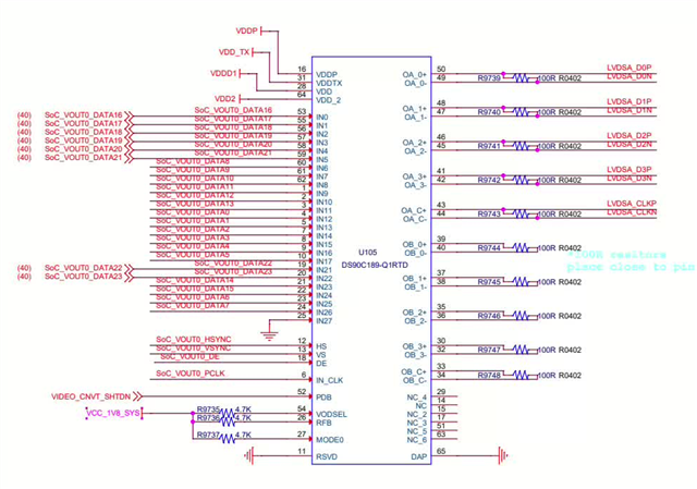
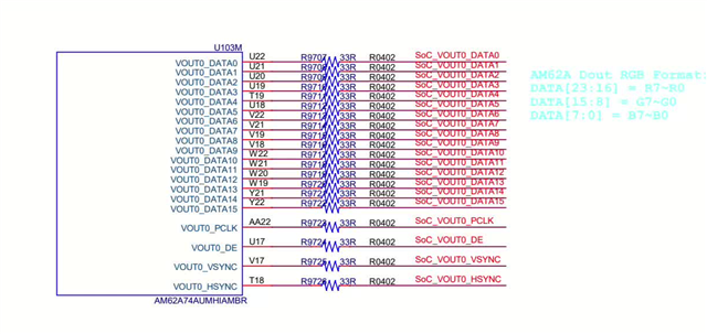
  • and here is the hardware of the soc dpi output:

  • HI,
    Please share your git diff and complete dmesg logs.

  • root@am62axx-evm:/opt/edgeai-gst-apps# kmstest
    Connector 0/@40: DPI-1
    Crtc 0/@38: 1280x720@79.24 76.782 1280/26/8/8/? 720/8/2/3/? 79 (79.24) 0x0 0x48
    Plane 0/@31: 0,0-1280x720
    Fb 49 1280x720-XR24
    press enter to exit

    diff --git a/drivers/gpu/drm/panel/panel-simple.c b/drivers/gpu/drm/panel/panel-simple.c
    old mode 100644
    new mode 100755
    index 7f13934f98c2..ac6297b56f52
    --- a/drivers/gpu/drm/panel/panel-simple.c
    +++ b/drivers/gpu/drm/panel/panel-simple.c
    @@ -589,7 +589,6 @@ static int panel_simple_probe(struct device *dev, const struct panel_desc *desc)
    if (!panel->ddc)
    return -EPROBE_DEFER;
    }
    -
    if (desc == &panel_dpi) {
    /* Handle the generic panel-dpi binding */
    err = panel_dpi_probe(dev, panel);
    @@ -600,8 +599,9 @@ static int panel_simple_probe(struct device *dev, const struct panel_desc *desc)
    if (!of_get_display_timing(dev->of_node, "panel-timing", &dt))
    panel_simple_parse_panel_timing_node(dev, panel, &dt);
    }
    -
    +
    connector_type = desc->connector_type;
    +
    /* Catch common mistakes for panels. */
    switch (connector_type) {
    case 0:
    @@ -3083,33 +3083,47 @@ static const struct panel_desc netron_dy_e231732 = {
    .bus_format = MEDIA_BUS_FMT_RGB666_1X18,
    };
    
    -static const struct drm_display_mode newhaven_nhd_43_480272ef_atxl_mode = {
    - .clock = 9000,
    - .hdisplay = 480,
    - .hsync_start = 480 + 2,
    - .hsync_end = 480 + 2 + 41,
    - .htotal = 480 + 2 + 41 + 2,
    - .vdisplay = 272,
    - .vsync_start = 272 + 2,
    - .vsync_end = 272 + 2 + 10,
    - .vtotal = 272 + 2 + 10 + 2,
    - .flags = DRM_MODE_FLAG_NVSYNC | DRM_MODE_FLAG_NHSYNC,
    +// static const struct drm_display_mode boe_av069hdt_a80_2dp0_mode = {
    +// .clock = 9000,
    +// .hdisplay = 480,
    +// .hsync_start = 480 + 2,
    +// .hsync_end = 480 + 2 + 41,
    +// .htotal = 480 + 2 + 41 + 2,
    +// .vdisplay = 272,
    +// .vsync_start = 272 + 2,
    +// .vsync_end = 272 + 2 + 10,
    +// .vtotal = 272 + 2 + 10 + 2,
    +// .flags = DRM_MODE_FLAG_NVSYNC | DRM_MODE_FLAG_NHSYNC,
    +// };
    +
    +static const struct drm_display_mode boe_av069hdt_a80_2dp0_mode = {
    + .clock = 76782,
    + .hdisplay = 1280,
    + .hsync_start = 1280 + 26,
    + .hsync_end = 1280 + 26 + 8,
    + .htotal = 1322,
    + .vdisplay = 720,
    + .vsync_start = 720 + 8,
    + .vsync_end = 720 + 8 + 2,
    + .vtotal = 733,
    + .flags = 0,
    };
    
    -static const struct panel_desc newhaven_nhd_43_480272ef_atxl = {
    - .modes = &newhaven_nhd_43_480272ef_atxl_mode,
    +static const struct panel_desc boe_av069hdt_a80_2dp0 = {
    + .modes = &boe_av069hdt_a80_2dp0_mode,
    .num_modes = 1,
    .bpc = 8,
    .size = {
    - .width = 95,
    - .height = 54,
    + .width = 154,
    + .height = 85,
    },
    - .bus_format = MEDIA_BUS_FMT_RGB888_1X24,
    - .bus_flags = DRM_BUS_FLAG_DE_HIGH | DRM_BUS_FLAG_PIXDATA_DRIVE_POSEDGE |
    - DRM_BUS_FLAG_SYNC_DRIVE_POSEDGE,
    + .bus_format = MEDIA_BUS_FMT_RGB888_1X24,
    + .bus_flags = DRM_BUS_FLAG_DE_HIGH | DRM_BUS_FLAG_PIXDATA_DRIVE_POSEDGE | DRM_BUS_FLAG_SYNC_DRIVE_POSEDGE,
    .connector_type = DRM_MODE_CONNECTOR_DPI,
    };
    
    +
    +
    static const struct display_timing nlt_nl192108ac18_02d_timing = {
    .pixelclock = { 130000000, 148350000, 163000000 },
    .hactive = { 1920, 1920, 1920 },
    @@ -4504,8 +4518,8 @@ static const struct of_device_id platform_of_match[] = {
    .compatible = "netron-dy,e231732",
    .data = &netron_dy_e231732,
    }, {
    - .compatible = "newhaven,nhd-4.3-480272ef-atxl",
    - .data = &newhaven_nhd_43_480272ef_atxl,
    + .compatible = "boe,AV069HDT-A80-2DP0",
    + .data = &boe_av069hdt_a80_2dp0,
    }, {
    .compatible = "nlt,nl192108ac18-02d",
    .data = &nlt_nl192108ac18_02d,


    diff --git a/arch/arm64/boot/dts/ti/k3-am62a7-sk.dts b/arch/arm64/boot/dts/ti/k3-am62a7-sk.dts
    old mode 100644
    new mode 100755
    index 1da8aa7f2e29..e47ad8320ef0
    --- a/arch/arm64/boot/dts/ti/k3-am62a7-sk.dts
    +++ b/arch/arm64/boot/dts/ti/k3-am62a7-sk.dts
    @@ -19,7 +19,7 @@ / {
    aliases {
    serial0 = &wkup_uart0;
    serial2 = &main_uart0;
    - serial3 = &main_uart1;
    + serial5 = &main_uart5;
    mmc0 = &sdhci0;
    mmc1 = &sdhci1;
    ethernet0 = &cpsw_port1;
    @@ -30,6 +30,7 @@ aliases {
    
    chosen {
    stdout-path = "serial2:115200n8";
    + bootargs = "console=ttyS2,115200n8 earlycon=ns16550a,mmio32,0x02800000 loglevel=4 root=/dev/mmcblk1p2 rw rootfstype=ext4 rootwait";
    };
    
    memory@80000000 {
    @@ -214,52 +215,17 @@ led-0 {
    };
    };
    
    - tlv320_mclk: clk-0 {
    - #clock-cells = <0>;
    - compatible = "fixed-clock";
    - clock-frequency = <12288000>;
    - };
    
    - hdmi0: connector-hdmi {
    - compatible = "hdmi-connector";
    - label = "hdmi";
    - type = "a";
    + panel {
    + compatible = "boe,AV069HDT-A80-2DP0";
    
    - port {
    - hdmi_connector_in: endpoint {
    - remote-endpoint = <&sii9022_out>;
    + port {
    + panel_in: endpoint {
    + remote-endpoint = <&dpi1_out>;
    + };
    };
    - };
    - };
    -
    - codec_audio: sound {
    - compatible = "simple-audio-card";
    - simple-audio-card,name = "AM62Ax-SKEVM";
    - simple-audio-card,widgets =
    - "Headphone", "Headphone Jack",
    - "Line", "Line In",
    - "Microphone", "Microphone Jack";
    - simple-audio-card,routing =
    - "Headphone Jack", "HPLOUT",
    - "Headphone Jack", "HPROUT",
    - "LINE1L", "Line In",
    - "LINE1R", "Line In",
    - "MIC3R", "Microphone Jack",
    - "Microphone Jack", "Mic Bias";
    - simple-audio-card,format = "dsp_b";
    - simple-audio-card,bitclock-master = <&sound_master>;
    - simple-audio-card,frame-master = <&sound_master>;
    - simple-audio-card,bitclock-inversion;
    -
    - simple-audio-card,cpu {
    - sound-dai = <&mcasp1>;
    - };
    -
    - sound_master: simple-audio-card,codec {
    - sound-dai = <&tlv320aic3106>;
    - clocks = <&tlv320_mclk>;
    - };
    };
    +
    };
    
    &mcu_pmx0 {
    @@ -330,6 +296,13 @@ AM62AX_IOPAD(0x0198, PIN_OUTPUT, 2) /* (B19) MCASP0_AXR2.UART1_RTSn */
    >;
    };
    
    + main_uart5_pins_default: main-uart5-default-pins {
    + pinctrl-single,pins = <
    + AM62AX_IOPAD(0x01d8, PIN_INPUT, 1) /* (B17) MCAN0_TX.UART5_RXD */
    + AM62AX_IOPAD(0x01dc, PIN_OUTPUT, 1) /* (C18) MCAN0_RX.UART5_TXD */
    + >;
    + };
    +
    main_i2c0_pins_default: main-i2c0-default-pins {
    pinctrl-single,pins = <
    AM62AX_IOPAD(0x1e0, PIN_INPUT_PULLUP, 0) /* (B16) I2C0_SCL */
    @@ -605,68 +578,6 @@ exp1: gpio@22 {
    "PD_I2C_IRQ", "IO_EXP_TEST_LED";
    };
    
    - tlv320aic3106: audio-codec@1b {
    - #sound-dai-cells = <0>;
    - compatible = "ti,tlv320aic3106";
    - reg = <0x1b>;
    - ai3x-micbias-vg = <1>; /* 2.0V */
    -
    - /* Regulators */
    - AVDD-supply = <&vcc_3v3_sys>;
    - IOVDD-supply = <&vcc_3v3_sys>;
    - DRVDD-supply = <&vcc_3v3_sys>;
    - DVDD-supply = <&buck5>;
    - };
    -
    - exp2: gpio@23 {
    - compatible = "ti,tca6424";
    - reg = <0x23>;
    - gpio-controller;
    - #gpio-cells = <2>;
    -
    - gpio-line-names = "", "",
    - "", "",
    - "", "",
    - "", "",
    - "WL_LT_EN", "CSI_RSTz",
    - "", "",
    - "", "",
    - "", "",
    - "SPI0_FET_SEL", "SPI0_FET_OE",
    - "RGMII2_BRD_CONN_DET", "CSI_SEL2",
    - "CSI_EN", "AUTO_100M_1000M_CONFIG",
    - "CSI_VLDO_SEL", "SoC_WLAN_SDIO_RST";
    - };
    -
    - sii9022: bridge-hdmi@3b {
    - compatible = "sil,sii9022";
    - reg = <0x3b>;
    - interrupt-parent = <&exp1>;
    - interrupts = <16 IRQ_TYPE_EDGE_FALLING>;
    - #sound-dai-cells = <0>;
    - sil,i2s-data-lanes = < 0 >;
    -
    - ports {
    - #address-cells = <1>;
    - #size-cells = <0>;
    -
    - port@0 {
    - reg = <0>;
    -
    - sii9022_in: endpoint {
    - remote-endpoint = <&dpi1_out>;
    - };
    - };
    -
    - port@1 {
    - reg = <1>;
    -
    - sii9022_out: endpoint {
    - remote-endpoint = <&hdmi_connector_in>;
    - };
    - };
    - };
    - };
    };
    
    &main_i2c2 {
    @@ -723,6 +634,14 @@ &main_uart1 {
    status = "reserved";
    };
    
    +&main_uart5 {
    + pinctrl-names = "default";
    + pinctrl-0 = <&main_uart5_pins_default>;
    + status = "okay";
    +};
    +
    +
    +
    /* Main Timer2 is used by C7x DSP */
    &main_timer2 {
    status = "reserved";
    @@ -819,7 +738,8 @@ hdmi0_dss: port@1 {
    reg = <1>;
    
    dpi1_out: endpoint {
    - remote-endpoint = <&sii9022_in>;
    +
    + remote-endpoint = <&panel_in>;
    };
    };
    };
    @@ -948,3 +868,66 @@ partition@7fc0000 {
    };
    };
    };
    +
    +
    +
    +
    +&{/} {
    + clk_imx219_fixed: imx219-xclk {
    + compatible = "fixed-clock";
    + #clock-cells = <0>;
    + clock-frequency = <25000000>;
    + };
    +};
    +
    +
    +&main_i2c2 {
    + #address-cells = <1>;
    + #size-cells = <0>;
    + status = "okay";
    +
    + camera@36 {
    + compatible = "sony,imx219";
    + reg = <0x36>;
    +
    + clocks = <&clk_imx219_fixed>;
    + clock-names = "xclk";
    + reset-gpios = <&exp1 13 GPIO_ACTIVE_HIGH>;
    + port {
    + csi2_cam0: endpoint {
    + remote-endpoint = <&csi2rx0_in_sensor>;
    + link-frequencies = /bits/ 64 <800000000>;
    + clock-lanes = <0>;
    + data-lanes = <1 2 3 4>;
    + };
    + };
    + };
    +};
    +
    +&cdns_csi2rx0 {
    + ports {
    + #address-cells = <1>;
    + #size-cells = <0>;
    +
    + csi0_port0: port@0 {
    + reg = <0>;
    + status = "okay";
    +
    + csi2rx0_in_sensor: endpoint {
    + remote-endpoint = <&csi2_cam0>;
    + clock-lanes = <0>;
    + data-lanes = <1 2 3 4>;
    + link-frequencies = /bits/ 64 <800000000>;
    + };
    + };
    + };
    +};
    +
    +&ti_csi2rx0 {
    + status = "okay";
    +};
    +
    +
    +&dphy0 {
    + status = "okay";
    +};

  • Looks like your kmstest is now working?

  • It is working. but no video output in the screen.
    i have no idea what the problem and how to check the problem


    how to check if the  screen is match with the DPI output or other problem.

  • You may probe to check if you are getting signals on DPI lines. That should be the case.
    With the above done, you may want to cross check your panel timing parameters as well as check the bus_format and bus_flags if they are compatible with your panel. Most likely issue is that your panel is not compatible with the configurations you have in your driver/dts.


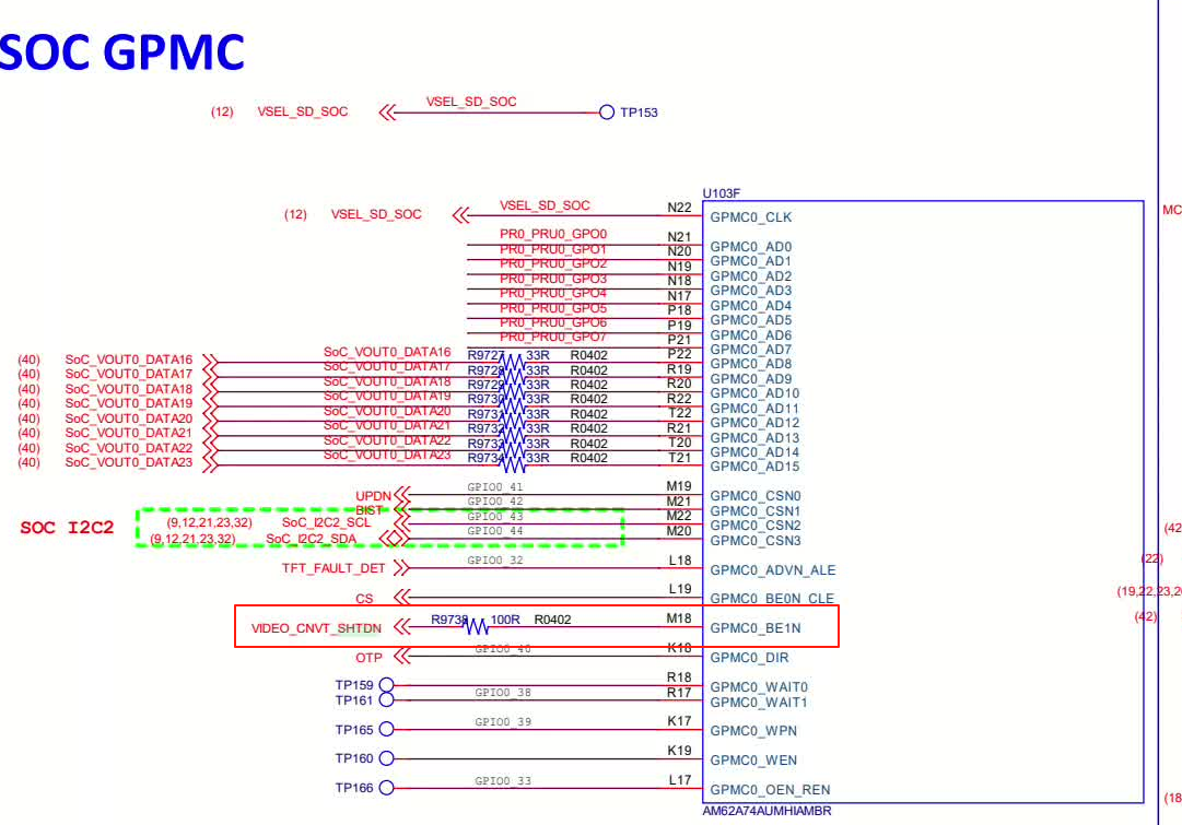
  • i check with the hardware that the pin GPMC0_BE1n/M18 is not set during startup. 


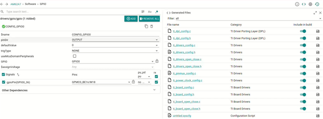
    i have check with the sysConfig. that i do not see that the register value below have be generated. can you help let me know where is get the pinctrl-single,pins value. thanks very much
    usr_led_pins_default: usr-led-default-pins {
    pinctrl-single,pins = <
    AM62AX_IOPAD(0x244, PIN_OUTPUT, 7) /* (D18) MMC1_SDWP.GPIO1_49 */
    >;
    };


    can you help me with the problem. thanks very much