This thread has been locked.

If you have a related question, please click the "Ask a related question" button in the top right corner. The newly created question will be automatically linked to this question.

TDA4VM: TDA4 AUTOSAR Dio config

Part Number: TDA4VM
Other Parts Discussed in Thread: SYSCONFIG

Tool/software:

Hello,


I have a question regarding the Dio handling using the MCUSW_01_03_00_10_CONFIG

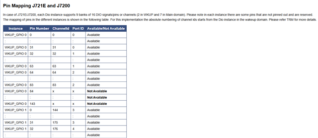
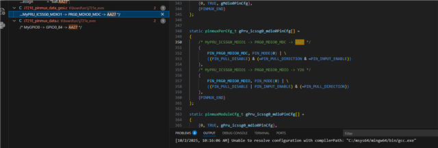
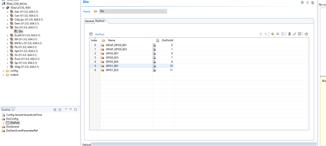
I can see Dio preconfigured but in a generation output I can see header and commens saying that there shall be more Ports and Channels defined:


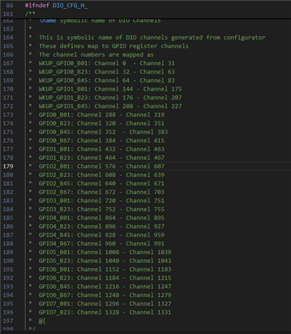
And these are the only ones defined:


If I want to use Port 0 Pin 81 i.e. currently I don't have that channel defined in the output.

Do you know if this is expected for me to fill in by myself, I mean all other banks and channels or just this .xdm is not complete one? How i.e. Port 0, Pin 81 is expected to be defined or there is some calculation behind and I should find it under existing definitions (just to mention there is no Channel ID 81 in any of these).

And I need that specific one Port 0, Pin 81 because I have application already existing but based on TI drivers and not ASR stack.

Do you know where could I find .xdm or .arxml with all of them for this target so I can integrate it more easily into Vector DaVinci Configurator?


Best Regards,

Tomislav

  • Hi,

    TI resource assigned to this post is currently out of office, please be aware that there will be a delay in response.

    Regards,

    kb

  • Hello KB,

    Do you have anyone else available for this topic, I am quite in a nick of time for client delivery tomorrow and woul appreciate if we could get some answers today.

    BTW one update so GPIO0_84 is something I would need to configure and SysConfig Tool says it is avaliable, it is AA27 pin ball. How come it is made reserved in Tresos:

    Should be used as SPI DAB pin for SPI6 over Motor Control Headers.

    Best Regards,

    Tomislav

  • Hello,

    Sorry for the delay, i was out of office last week.

    BTW one update so GPIO0_84 is something I would need to configure and SysConfig Tool says it is avaliable, it is AA27 pin ball. How come it is made reserved in Tresos:

    GPIO Not Supported Features as per TRM


    • The following apply to WKUP_GPIOu (u = 0, 1)
    – WKUP_GPIOu_[84:143] are not pinned out.
    – Interrupts [84:143] are not pinned out.
    – Bank Interrupts [8:6] are not pinned out.
    – From WKUP_GPO[68] to WKUP_GPO[83] buffer is output only.


    • The following apply to GPIOn (n = 0, 2, 4, 6):
    – GPIOn_[128:143] are not pinned out.
    – Interrupts [128:143] are not pinned out.
    – Bank Interrupt 8 is not pinned out.


    • The following apply to GPIOm (m = 1, 3, 5, 7):
    – GPIOm_[36:143] are not pinned out.
    – Interrupts [36:143] are not pinned out.
    – Bank Interrupts [8:2] are not pinned out.

    The Pin GPIO0_84 you are mentioning is main domain GPIO0 and in the below the reserved one is WKUP_GPIO0 both are different GPIO's.

    How come it is made reserved in Tresos:

    Regards

    Tarun Mukesh

  • Hello Tarun Mukesh,

    Thank you I understood. I have reconfigured to match GPIO0 and Dio is looking okay.

    Now the issue I have is realted to ISR routing. Can you guide me how it is expected to be reouted for MCSPI6 from MAIN domain to MCU Core 0?

    here is the code snippet I have put together:

    void Spi_InterruptConfig(void)
    {
      struct tisci_msg_rm_irq_set_req     rmIrqReq;
      struct tisci_msg_rm_irq_set_resp    rmIrqResp;
      uint32 retVal;
    
      /* If the SPI instance is not in MCU domain, the interrupt router will
         have to be configured */
      /* Set the destination interrupt */
    
      /* MAIN MCSPI6 routing */
      rmIrqReq.valid_params           = TISCI_MSG_VALUE_RM_DST_ID_VALID;
      rmIrqReq.valid_params          |= TISCI_MSG_VALUE_RM_DST_HOST_IRQ_VALID;
      rmIrqReq.src_id                 = TISCI_DEV_MCSPI6;
      rmIrqReq.global_event           = 0U;
      /* Src Index 0 - intr_spi  */
      rmIrqReq.src_index              = 0U;
      rmIrqReq.dst_id                 = TISCI_DEV_MCU_R5FSS0_CORE0;
      rmIrqReq.dst_host_irq           = CSLR_MCU_R5FSS0_CORE0_INTR_MAIN2MCU_LVL_INTRTR0_OUTL_0 + 0U;
      rmIrqReq.ia_id                  = 0U;
      rmIrqReq.vint                   = 0U;
      rmIrqReq.vint_status_bit_index  = 0U;
      rmIrqReq.secondary_host         = TISCI_MSG_VALUE_RM_UNUSED_SECONDARY_HOST;
      retVal = Sciclient_rmIrqSet(&rmIrqReq, &rmIrqResp, SCICLIENT_SERVICE_WAIT_FOREVER);
      if((uint32)0 != retVal)
      {
        while(1);
      }
    }

    so from my understanding MAIN2MCU_OUTL_0 can be configured to route any R5FSS0_INTR_IN (which in this case should be 198 from docs for the MCSPI6) but it is not hitting ISR.

    Can you tell me what should be also the Interrupt source ID from the Os perspective in your solution?

    PS. I also tried to configure MAIN2MCU_OUTL0 +38 (which then corresponds to 198 from the R5FSS0_CORE0_INTR_IN_198) but gets stuck in the while loop.

    Thank you Tarun Mukesh, I appreciate your support.

    BR,

    Tomislav

  • Hello,

    I suggest you raise another E2E thread since this one is DIO config rather than SPI interrupt routing.

    The rmIrqReq.dst_host_irq can be in the range of 160-223 . The irq number selected should not be used by any other application.

    The same irq number you have to register in Davinci configurator as well.

    PS. I also tried to configure MAIN2MCU_OUTL0 +38 (which then corresponds to 198 from the R5FSS0_CORE0_INTR_IN_198) but gets stuck in the while loop.

    May be another resource have already used this 198 interrupt thats when it will fail.

    Regards

    Tarun mukesh