AM6442: Regarding the handling of unconnected signals that are not specified in the Pin Connectivity Requirements.

Part Number: AM6442

Tool/software:

Hi   Dear  TI Experts,

Regarding the handling of unconnected signals that are not specified in the Pin Connectivity Requirements.

For the following unused signals, is an open-collector configuration sufficient, or do they require a pull-down resistor?

or VSS connection?

1.SPI Signal

SPI0_CLK
SPI0_D0
SPI0_D1
SPI0_CS0
SPI0_CS1

2.MCAN Signal

MCAN0_RX
MCAN0_TX
MCAN1_RX
MCAN1_TX

3.UART Signal

UART0_CTSN
UART0_RTSN
UART0_RXD
UART0_TXD

4.MCU_OSC

MCU_OSC0_XI
MCU_OSC0_XO

5.MCU UART Signal

MCU_UART0_RXD
MCU_UART0_TXD
MCU_UART0_CTSN
MCU_UART0_RTSN

6.MCU System Signal

MCU_RESETSTATZ

7.System Signal

EXTINTN

8.MCU System Signal

MCU_SAFETY_ERRORN

  • Hello KIYOSHI KOGURE

    Thank you for the query.

    Please refer below:

    Schematic Design guidelines and Schematics review checklist reference 

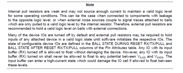
    When a trace is connected to the processor pins (IO pads) and the IOs are not being actively driven (floating),
    a parallel pull 47kΩ is recommended. Processor IO buffers are (TX (Output) and RX (Input) are disabled during
    and after reset and internal pulls (pullup and pulldown)) turned off during reset and after reset. The IOs are in a
    high impedance state, effectively behaving as an antenna that can pick up noise. Without a parallel pull, the IOs
    are in high impedance state. High impedance makes noise to couple energy easily on the floating signal trace
    and develop a potential that can exceed the IO recommended operating conditions. The potential creates an
    electrical over-stress (EOS) on the IOs. Electrostatic discharge (ESD) protection circuits internal to the processor
    were designed to only protect the device from ESD during handling before being installed on a PCB.

    Processor Data sheet reference:

    Regards,

    reenivasa