This thread has been locked.

If you have a related question, please click the "Ask a related question" button in the top right corner. The newly created question will be automatically linked to this question.

AM62A7-Q1: [AM62A7]The SOC receives the raw CSI data from the FPGA.

Part Number: AM62A7-Q1

Hello,
The Linux system is already running on our custom board.

The following diagram shows our hardware connection.
Use CSI2 DPHY 1.5Gbps, 4 lane
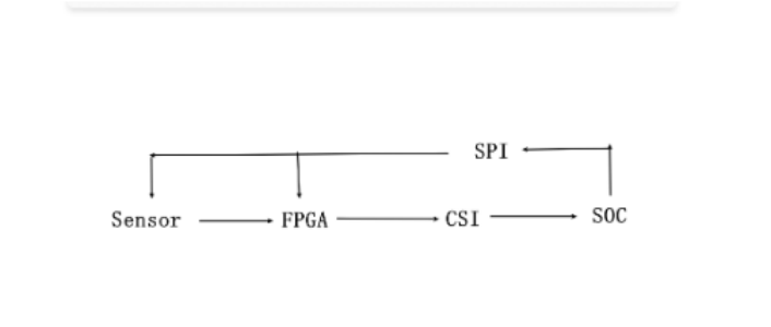
image.png


I have a few questions I'd like to ask.
1.Is there a driver in the SDK that I can refer to?
2.How can I obtain the raw data from CSI? 
I modified the driver based on the OV5640 driver for FPGA (removing IIC control,PM, Regulator,only reserve v4l2 subdev). 
During the debugging phase, the FPGA continuously sends data and does not require control.
Our data format is custom-defined; I want to directly obtain the raw data.

The following links are already connected.
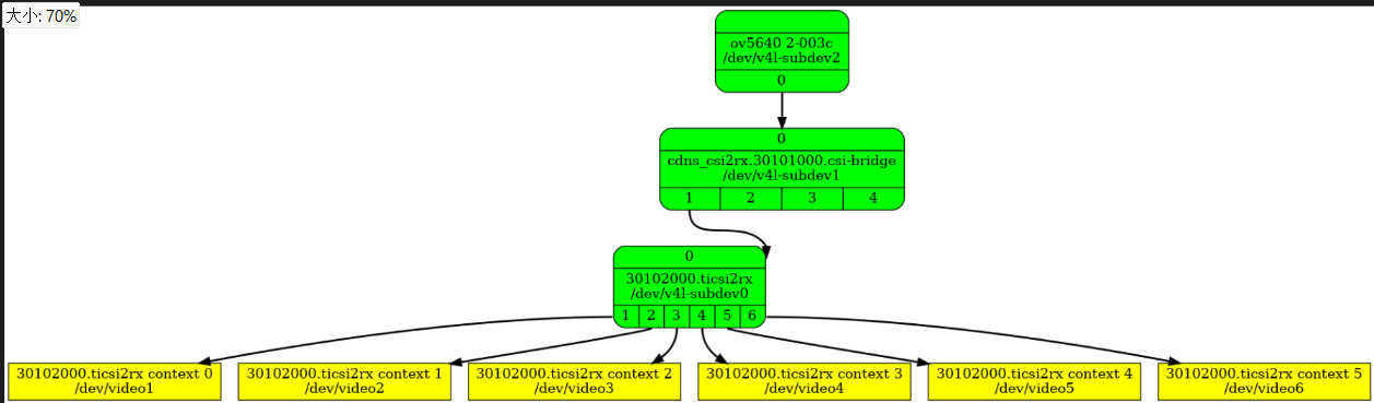
image.png


root@am62axx-evm:~# lsmod | grep "ov5640"
ov5640                 12288  0

root@am62axx-evm:~# media-ctl -d /dev/media0 -p
Media controller API version 6.12.35

Media device information
------------------------
driver          j721e-csi2rx
model           TI-CSI2RX
serial          
bus info        platform:30102000.ticsi2rx
hw revision     0x1
driver version  6.12.35

Device topology
- entity 1: 30102000.ticsi2rx (7 pads, 7 links, 1 route)
            type V4L2 subdev subtype Unknown flags 0
            device node name /dev/v4l-subdev0
        routes:
                0/0 -> 1/0 [ACTIVE]
        pad0: SINK
                [stream:0 fmt:UYVY8_1X16/640x480 field:none colorspace:srgb xfer:srgb ycbcr:601 quantization:lim-range]
                <- "cdns_csi2rx.30101000.csi-bridge":1 [ENABLED,IMMUTABLE]
        pad1: SOURCE
                [stream:0 fmt:UYVY8_1X16/640x480 field:none colorspace:srgb xfer:srgb ycbcr:601 quantization:lim-range]
                -> "30102000.ticsi2rx context 0":0 [ENABLED,IMMUTABLE]
        pad2: SOURCE
                -> "30102000.ticsi2rx context 1":0 [ENABLED,IMMUTABLE]
        pad3: SOURCE
                -> "30102000.ticsi2rx context 2":0 [ENABLED,IMMUTABLE]
        pad4: SOURCE
                -> "30102000.ticsi2rx context 3":0 [ENABLED,IMMUTABLE]
        pad5: SOURCE
                -> "30102000.ticsi2rx context 4":0 [ENABLED,IMMUTABLE]
        pad6: SOURCE
                -> "30102000.ticsi2rx context 5":0 [ENABLED,IMMUTABLE]

- entity 9: cdns_csi2rx.30101000.csi-bridge (5 pads, 2 links, 1 route)
            type V4L2 subdev subtype Unknown flags 0
            device node name /dev/v4l-subdev1
        routes:
                0/0 -> 1/0 [ACTIVE]
        pad0: SINK
                [stream:0 fmt:UYVY8_1X16/640x480 field:none colorspace:srgb xfer:srgb ycbcr:601 quantization:lim-range]
                <- "ov5640 2-003c":0 [ENABLED,IMMUTABLE]
        pad1: SOURCE
                [stream:0 fmt:UYVY8_1X16/640x480 field:none colorspace:srgb xfer:srgb ycbcr:601 quantization:lim-range]
                -> "30102000.ticsi2rx":0 [ENABLED,IMMUTABLE]
        pad2: SOURCE
        pad3: SOURCE
        pad4: SOURCE

- entity 15: ov5640 2-003c (1 pad, 1 link, 0 routes)
             type V4L2 subdev subtype Sensor flags 0
             device node name /dev/v4l-subdev2
        pad0: SOURCE
                [stream:0 fmt:UYVY8_1X16/640x480@1/30 field:none colorspace:srgb xfer:srgb ycbcr:601 quantization:full-range
                 crop.bounds:(0,0)/0x0
                 crop:(0,0)/0x0
                 compose.bounds:(0,0)/0x0
                 compose:(0,0)/0x0]
                -> "cdns_csi2rx.30101000.csi-bridge":0 [ENABLED,IMMUTABLE]

- entity 21: 30102000.ticsi2rx context 0 (1 pad, 1 link)
             type Node subtype V4L flags 0
             device node name /dev/video1
        pad0: SINK
                <- "30102000.ticsi2rx":1 [ENABLED,IMMUTABLE]

- entity 27: 30102000.ticsi2rx context 1 (1 pad, 1 link)
             type Node subtype V4L flags 0
             device node name /dev/video2
        pad0: SINK
                <- "30102000.ticsi2rx":2 [ENABLED,IMMUTABLE]

- entity 33: 30102000.ticsi2rx context 2 (1 pad, 1 link)
             type Node subtype V4L flags 0
             device node name /dev/video3
        pad0: SINK
                <- "30102000.ticsi2rx":3 [ENABLED,IMMUTABLE]

- entity 39: 30102000.ticsi2rx context 3 (1 pad, 1 link)
             type Node subtype V4L flags 0
             device node name /dev/video4
        pad0: SINK
                <- "30102000.ticsi2rx":4 [ENABLED,IMMUTABLE]

- entity 45: 30102000.ticsi2rx context 4 (1 pad, 1 link)
             type Node subtype V4L flags 0
             device node name /dev/video5
        pad0: SINK
                <- "30102000.ticsi2rx":5 [ENABLED,IMMUTABLE]

- entity 51: 30102000.ticsi2rx context 5 (1 pad, 1 link)
             type Node subtype V4L flags 0
             device node name /dev/video6
        pad0: SINK
                <- "30102000.ticsi2rx":6 [ENABLED,IMMUTABLE]

root@am62axx-evm:~# 
root@am62axx-evm:~# v4l2-ctl --device=/dev/video1 --info
Driver Info:
        Driver name      : j721e-csi2rx
        Card type        : j721e-csi2rx
        Bus info         : platform:30102000.ticsi2rx
        Driver version   : 6.12.35
        Capabilities     : 0xa4200001
                Video Capture
                I/O MC
                Streaming
                Extended Pix Format
                Device Capabilities
        Device Caps      : 0x24200001
                Video Capture
                I/O MC
                Streaming
                Extended Pix Format
Media Driver Info:
        Driver name      : j721e-csi2rx
        Model            : TI-CSI2RX
        Serial           : 
        Bus info         : platform:30102000.ticsi2rx
        Media version    : 6.12.35
        Hardware revision: 0x00000001 (1)
        Driver version   : 6.12.35
Interface Info:
        ID               : 0x03000017
        Type             : V4L Video
Entity Info:
        ID               : 0x00000015 (21)
        Name             : 30102000.ticsi2rx context 0
        Function         : V4L2 I/O
        Pad 0x01000016   : 0: Sink
          Link 0x02000019: from remote pad 0x1000003 of entity '30102000.ticsi2rx' (Video Interface Bridge): Data, Enabled, Immutable

root@am62axx-evm:~# v4l2-ctl --list-devices
j721e-csi2rx (platform:30102000.ticsi2rx):
        /dev/video1
        /dev/video2
        /dev/video3
        /dev/video4
        /dev/video5
        /dev/video6
        /dev/media0

e5010 (platform:fd20000.jpeg-encoder):
        /dev/video0

root@am62axx-evm:~# yavta -c -Fcapture -s 640x480 -f UYVY /dev/video1
Device /dev/video1 opened.
Device `j721e-csi2rx' on `platform:30102000.ticsi2rx' (driver 'j721e-csi2rx') supports video, capture, without mplanes.
Video format set: UYVY (59565955) 640x480 (stride 1280) field none buffer size 614400
Video format: UYVY (59565955) 640x480 (stride 1280) field none buffer size 614400
8 buffers requested.
length: 614400 offset: 0 timestamp type/source: mono/EoF
Buffer 0/0 mapped at address 0xffff99d3a000.
length: 614400 offset: 32768 timestamp type/source: mono/EoF
Buffer 1/0 mapped at address 0xffff99ca4000.
length: 614400 offset: 65536 timestamp type/source: mono/EoF
Buffer 2/0 mapped at address 0xffff99c0e000.
length: 614400 offset: 98304 timestamp type/source: mono/EoF
Buffer 3/0 mapped at address 0xffff99b78000.
length: 614400 offset: 131072 timestamp type/source: mono/EoF
Buffer 4/0 mapped at address 0xffff99ae2000.
length: 614400 offset: 163840 timestamp type/source: mono/EoF
Buffer 5/0 mapped at address 0xffff99a4c000.
length: 614400 offset: 196608 timestamp type/source: mono/EoF
Buffer 6/0 mapped at address 0xffff999b6000.
length: 614400 offset: 229376 timestamp type/source: mono/EoF
Buffer 7/0 mapped at address 0xffff99920000.
  • Hi Slowby,

    1. Is there a driver in the SDK that I can refer to?

    You can use imx219.c as reference driver. 

    2. How can I obtain the raw data from CSI? 

    Please refer the below document

    Link:- https://software-dl.ti.com/processor-sdk-linux/esd/AM62AX/latest/exports/docs/linux/Foundational_Components/Kernel/Kernel_Drivers/Camera/CSI2RX.html

    Regards,

    Dilna K

  • Hello,DiLna

    I modified it to use SPI control, referencing the IMX219(The data is actually sent from the FPGA; the name doesn't matter.).

    After checking the link channel, the connection was found to be normal.

    imx219 module is used.


    root@am62axx-evm:~# lsmod | grep imx219
    imx219                 16384  1
    root@am62axx-evm:~# v4l2-ctl --list-devices
    j721e-csi2rx (platform:30102000.ticsi2rx):
            /dev/video1
            /dev/video2
            /dev/video3
            /dev/video4
            /dev/video5
            /dev/video6
            /dev/media0
    
    e5010 (platform:fd20000.jpeg-encoder):
            /dev/video0
    
    root@am62axx-evm:~# v4l2-ctl -d /dev/video1 --list-formats-ext
    ioctl: VIDIOC_ENUM_FMT
            Type: Video Capture
    
            [0]: 'YUYV' (YUYV 4:2:2)
                    Size: Stepwise 1x1 - 8192x16384 with step 1/1
            [1]: 'UYVY' (UYVY 4:2:2)
                    Size: Stepwise 1x1 - 8192x16384 with step 1/1
            [2]: 'YVYU' (YVYU 4:2:2)
                    Size: Stepwise 1x1 - 8192x16384 with step 1/1
            [3]: 'VYUY' (VYUY 4:2:2)
                    Size: Stepwise 1x1 - 8192x16384 with step 1/1
            [4]: 'BA81' (8-bit Bayer BGBG/GRGR)
                    Size: Stepwise 1x1 - 16384x16384 with step 1/1
            [5]: 'GBRG' (8-bit Bayer GBGB/RGRG)
                    Size: Stepwise 1x1 - 16384x16384 with step 1/1
            [6]: 'GRBG' (8-bit Bayer GRGR/BGBG)
                    Size: Stepwise 1x1 - 16384x16384 with step 1/1
            [7]: 'RGGB' (8-bit Bayer RGRG/GBGB)
                    Size: Stepwise 1x1 - 16384x16384 with step 1/1
            [8]: 'GREY' (8-bit Greyscale)
                    Size: Stepwise 1x1 - 16384x16384 with step 1/1
            [9]: 'BG10' (10-bit Bayer BGBG/GRGR)
                    Size: Stepwise 1x1 - 8192x16384 with step 1/1
            [10]: 'GB10' (10-bit Bayer GBGB/RGRG)
                    Size: Stepwise 1x1 - 8192x16384 with step 1/1
            [11]: 'BA10' (10-bit Bayer GRGR/BGBG)
                    Size: Stepwise 1x1 - 8192x16384 with step 1/1
            [12]: 'RG10' (10-bit Bayer RGRG/GBGB)
                    Size: Stepwise 1x1 - 8192x16384 with step 1/1
            [13]: 'RGI0' (10-bit Bayer RGBG/GIrGIr)
                    Size: Stepwise 1x1 - 8192x16384 with step 1/1
            [14]: 'GRI0' (10-bit Bayer GRGB/IrGIrG)
                    Size: Stepwise 1x1 - 8192x16384 with step 1/1
            [15]: 'BGI0' (10-bit Bayer BGRG/GIrGIr)
                    Size: Stepwise 1x1 - 8192x16384 with step 1/1
            [16]: 'GBI0' (10-bit Bayer GBGR/IrGIrG)
                    Size: Stepwise 1x1 - 8192x16384 with step 1/1
            [17]: 'GIR0' (10-bit Bayer GIrGIr/RGBG)
                    Size: Stepwise 1x1 - 8192x16384 with step 1/1
            [18]: 'IGR0' (10-bit Bayer IrGIrG/GRGB)
                    Size: Stepwise 1x1 - 8192x16384 with step 1/1
            [19]: 'GIB0' (10-bit Bayer GIrGIr/BGRG)
                    Size: Stepwise 1x1 - 8192x16384 with step 1/1
            [20]: 'IGB0' (10-bit Bayer IrGIrG/GBGR)
                    Size: Stepwise 1x1 - 8192x16384 with step 1/1
            [21]: 'BG12' (12-bit Bayer BGBG/GRGR)
                    Size: Stepwise 1x1 - 8192x16384 with step 1/1
            [22]: 'GB12' (12-bit Bayer GBGB/RGRG)
                    Size: Stepwise 1x1 - 8192x16384 with step 1/1
            [23]: 'BA12' (12-bit Bayer GRGR/BGBG)
                    Size: Stepwise 1x1 - 8192x16384 with step 1/1
            [24]: 'RG12' (12-bit Bayer RGRG/GBGB)
                    Size: Stepwise 1x1 - 8192x16384 with step 1/1
            [25]: 'RGBR' (16-bit RGB 5-6-5 BE)
                    Size: Stepwise 1x1 - 8192x16384 with step 1/1
            [26]: 'Y10 ' (10-bit Greyscale)
                    Size: Stepwise 1x1 - 8192x16384 with step 1/1
            [27]: 'XR24' (32-bit BGRX 8-8-8-8)
                    Size: Stepwise 1x1 - 4096x16384 with step 1/1
            [28]: 'XB24' (32-bit RGBX 8-8-8-8)
                    Size: Stepwise 1x1 - 4096x16384 with step 1/1
    root@am62axx-evm:~# v4l2-ctl --device=/dev/video1 --info 
    Driver Info:
            Driver name      : j721e-csi2rx
            Card type        : j721e-csi2rx
            Bus info         : platform:30102000.ticsi2rx
            Driver version   : 6.12.35
            Capabilities     : 0xa4200001
                    Video Capture
                    I/O MC
                    Streaming
                    Extended Pix Format
                    Device Capabilities
            Device Caps      : 0x24200001
                    Video Capture
                    I/O MC
                    Streaming
                    Extended Pix Format
    Media Driver Info:
            Driver name      : j721e-csi2rx
            Model            : TI-CSI2RX
            Serial           : 
            Bus info         : platform:30102000.ticsi2rx
            Media version    : 6.12.35
            Hardware revision: 0x00000001 (1)
            Driver version   : 6.12.35
    Interface Info:
            ID               : 0x03000017
            Type             : V4L Video
    Entity Info:
            ID               : 0x00000015 (21)
            Name             : 30102000.ticsi2rx context 0
            Function         : V4L2 I/O
            Pad 0x01000016   : 0: Sink
              Link 0x02000019: from remote pad 0x1000003 of entity '30102000.ticsi2rx' (Video Interface Bridge): Data, Enabled, Immutable
    root@am62axx-evm:~# media-ctl -d /dev/media0 -p
    Media controller API version 6.12.35
    
    Media device information
    ------------------------
    driver          j721e-csi2rx
    model           TI-CSI2RX
    serial          
    bus info        platform:30102000.ticsi2rx
    hw revision     0x1
    driver version  6.12.35
    
    Device topology
    - entity 1: 30102000.ticsi2rx (7 pads, 7 links, 1 route)
                type V4L2 subdev subtype Unknown flags 0
                device node name /dev/v4l-subdev0
            routes:
                    0/0 -> 1/0 [ACTIVE]
            pad0: SINK
                    [stream:0 fmt:UYVY8_1X16/640x480 field:none colorspace:srgb xfer:srgb ycbcr:601 quantization:lim-range]
                    <- "cdns_csi2rx.30101000.csi-bridge":1 [ENABLED,IMMUTABLE]
            pad1: SOURCE
                    [stream:0 fmt:UYVY8_1X16/640x480 field:none colorspace:srgb xfer:srgb ycbcr:601 quantization:lim-range]
                    -> "30102000.ticsi2rx context 0":0 [ENABLED,IMMUTABLE]
            pad2: SOURCE
                    -> "30102000.ticsi2rx context 1":0 [ENABLED,IMMUTABLE]
            pad3: SOURCE
                    -> "30102000.ticsi2rx context 2":0 [ENABLED,IMMUTABLE]
            pad4: SOURCE
                    -> "30102000.ticsi2rx context 3":0 [ENABLED,IMMUTABLE]
            pad5: SOURCE
                    -> "30102000.ticsi2rx context 4":0 [ENABLED,IMMUTABLE]
            pad6: SOURCE
                    -> "30102000.ticsi2rx context 5":0 [ENABLED,IMMUTABLE]
    
    - entity 9: cdns_csi2rx.30101000.csi-bridge (5 pads, 2 links, 1 route)
                type V4L2 subdev subtype Unknown flags 0
                device node name /dev/v4l-subdev1
            routes:
                    0/0 -> 1/0 [ACTIVE]
            pad0: SINK
                    [stream:0 fmt:UYVY8_1X16/640x480 field:none colorspace:srgb xfer:srgb ycbcr:601 quantization:lim-range]
                    <- "imx219 spi2.1":0 [ENABLED,IMMUTABLE]
            pad1: SOURCE
                    [stream:0 fmt:UYVY8_1X16/640x480 field:none colorspace:srgb xfer:srgb ycbcr:601 quantization:lim-range]
                    -> "30102000.ticsi2rx":0 [ENABLED,IMMUTABLE]
            pad2: SOURCE
            pad3: SOURCE
            pad4: SOURCE
    
    - entity 15: imx219 spi2.1 (1 pad, 1 link, 0 routes)
                 type V4L2 subdev subtype Sensor flags 0
                 device node name /dev/v4l-subdev2
            pad0: SOURCE
                    [stream:0 fmt:SRGGB10_1X10/3280x2464 field:none colorspace:raw xfer:none ycbcr:601 quantization:full-range
                     crop.bounds:(8,8)/3280x2464
                     crop:(8,8)/3280x2464]
                    -> "cdns_csi2rx.30101000.csi-bridge":0 [ENABLED,IMMUTABLE]
    
    - entity 21: 30102000.ticsi2rx context 0 (1 pad, 1 link)
                 type Node subtype V4L flags 0
                 device node name /dev/video1
            pad0: SINK
                    <- "30102000.ticsi2rx":1 [ENABLED,IMMUTABLE]
    
    - entity 27: 30102000.ticsi2rx context 1 (1 pad, 1 link)
                 type Node subtype V4L flags 0
                 device node name /dev/video2
            pad0: SINK
                    <- "30102000.ticsi2rx":2 [ENABLED,IMMUTABLE]
    
    - entity 33: 30102000.ticsi2rx context 2 (1 pad, 1 link)
                 type Node subtype V4L flags 0
                 device node name /dev/video3
            pad0: SINK
                    <- "30102000.ticsi2rx":3 [ENABLED,IMMUTABLE]
    
    - entity 39: 30102000.ticsi2rx context 3 (1 pad, 1 link)
                 type Node subtype V4L flags 0
                 device node name /dev/video4
            pad0: SINK
                    <- "30102000.ticsi2rx":4 [ENABLED,IMMUTABLE]
    
    - entity 45: 30102000.ticsi2rx context 4 (1 pad, 1 link)
                 type Node subtype V4L flags 0
                 device node name /dev/video5
            pad0: SINK
                    <- "30102000.ticsi2rx":5 [ENABLED,IMMUTABLE]
    
    - entity 51: 30102000.ticsi2rx context 5 (1 pad, 1 link)
                 type Node subtype V4L flags 0
                 device node name /dev/video6
            pad0: SINK
                    <- "30102000.ticsi2rx":6 [ENABLED,IMMUTABLE]


    and than i executed the following commands.

    However, it seems that the frame-*.bin file was not generated, and yavta the process appears to be stuck.

    root@am62axx-evm:~# media-ctl --set-v4l2 '"30102000.ticsi2rx":0[fmt:SRGGB8_1X8/1920x1080]'
    root@am62axx-evm:~# media-ctl --set-v4l2 '"imx219 spi2.1":0[fmt:SRGGB8_1X8/1920x1080]'
    root@am62axx-evm:~# media-ctl -d /dev/media0 -p
    Media controller API version 6.12.35
    
    Media device information
    ------------------------
    driver          j721e-csi2rx
    model           TI-CSI2RX
    serial          
    bus info        platform:30102000.ticsi2rx
    hw revision     0x1
    driver version  6.12.35
    
    Device topology
    - entity 1: 30102000.ticsi2rx (7 pads, 7 links, 1 route)
                type V4L2 subdev subtype Unknown flags 0
                device node name /dev/v4l-subdev0
            routes:
                    0/0 -> 1/0 [ACTIVE]
            pad0: SINK
                    [stream:0 fmt:SRGGB8_1X8/1920x1080 field:none]
                    <- "cdns_csi2rx.30101000.csi-bridge":1 [ENABLED,IMMUTABLE]
            pad1: SOURCE
                    [stream:0 fmt:SRGGB8_1X8/1920x1080 field:none]
                    -> "30102000.ticsi2rx context 0":0 [ENABLED,IMMUTABLE]
            pad2: SOURCE
                    -> "30102000.ticsi2rx context 1":0 [ENABLED,IMMUTABLE]
            pad3: SOURCE
                    -> "30102000.ticsi2rx context 2":0 [ENABLED,IMMUTABLE]
            pad4: SOURCE
                    -> "30102000.ticsi2rx context 3":0 [ENABLED,IMMUTABLE]
            pad5: SOURCE
                    -> "30102000.ticsi2rx context 4":0 [ENABLED,IMMUTABLE]
            pad6: SOURCE
                    -> "30102000.ticsi2rx context 5":0 [ENABLED,IMMUTABLE]
    
    - entity 9: cdns_csi2rx.30101000.csi-bridge (5 pads, 2 links, 1 route)
                type V4L2 subdev subtype Unknown flags 0
                device node name /dev/v4l-subdev1
            routes:
                    0/0 -> 1/0 [ACTIVE]
            pad0: SINK
                    [stream:0 fmt:SRGGB8_1X8/1920x1080 field:none colorspace:raw xfer:none ycbcr:601 quantization:full-range]
                    <- "imx219 spi2.1":0 [ENABLED,IMMUTABLE]
            pad1: SOURCE
                    [stream:0 fmt:SRGGB8_1X8/1920x1080 field:none colorspace:raw xfer:none ycbcr:601 quantization:full-range]
                    -> "30102000.ticsi2rx":0 [ENABLED,IMMUTABLE]
            pad2: SOURCE
            pad3: SOURCE
            pad4: SOURCE
    
    - entity 15: imx219 spi2.1 (1 pad, 1 link, 0 routes)
                 type V4L2 subdev subtype Sensor flags 0
                 device node name /dev/v4l-subdev2
            pad0: SOURCE
                    [stream:0 fmt:SRGGB8_1X8/1920x1080 field:none colorspace:raw xfer:none ycbcr:601 quantization:full-range
                     crop.bounds:(8,8)/3280x2464
                     crop:(688,160)/1920x2160]
                    -> "cdns_csi2rx.30101000.csi-bridge":0 [ENABLED,IMMUTABLE]
    
    - entity 21: 30102000.ticsi2rx context 0 (1 pad, 1 link)
                 type Node subtype V4L flags 0
                 device node name /dev/video1
            pad0: SINK
                    <- "30102000.ticsi2rx":1 [ENABLED,IMMUTABLE]
    
    - entity 27: 30102000.ticsi2rx context 1 (1 pad, 1 link)
                 type Node subtype V4L flags 0
                 device node name /dev/video2
            pad0: SINK
                    <- "30102000.ticsi2rx":2 [ENABLED,IMMUTABLE]
    
    - entity 33: 30102000.ticsi2rx context 2 (1 pad, 1 link)
                 type Node subtype V4L flags 0
                 device node name /dev/video3
            pad0: SINK
                    <- "30102000.ticsi2rx":3 [ENABLED,IMMUTABLE]
    
    - entity 39: 30102000.ticsi2rx context 3 (1 pad, 1 link)
                 type Node subtype V4L flags 0
                 device node name /dev/video4
            pad0: SINK
                    <- "30102000.ticsi2rx":4 [ENABLED,IMMUTABLE]
    
    - entity 45: 30102000.ticsi2rx context 4 (1 pad, 1 link)
                 type Node subtype V4L flags 0
                 device node name /dev/video5
            pad0: SINK
                    <- "30102000.ticsi2rx":5 [ENABLED,IMMUTABLE]
    
    - entity 51: 30102000.ticsi2rx context 5 (1 pad, 1 link)
                 type Node subtype V4L flags 0
                 device node name /dev/video6
            pad0: SINK
                    <- "30102000.ticsi2rx":6 [ENABLED,IMMUTABLE]
    
    root@am62axx-evm:~# cd /usr/app/
    root@am62axx-evm:/usr/app# yavta -s 1920x1080 -f SRGGB8 /dev/video1 -c10
    Device /dev/video1 opened.
    Device `j721e-csi2rx' on `platform:30102000.ticsi2rx' (driver 'j721e-csi2rx') supports video, capture, without mplanes.
    Video format set: SRGGB8 (42474752) 1920x1080 (stride 1920) field none buffer size 2073600
    Video format: SRGGB8 (42474752) 1920x1080 (stride 1920) field none buffer size 2073600
    8 buffers requested.
    length: 2073600 offset: 0 timestamp type/source: mono/EoF
    Buffer 0/0 mapped at address 0xffffab565000.
    length: 2073600 offset: 32768 timestamp type/source: mono/EoF
    Buffer 1/0 mapped at address 0xffffab36a000.
    length: 2073600 offset: 65536 timestamp type/source: mono/EoF
    Buffer 2/0 mapped at address 0xffffab16f000.
    length: 2073600 offset: 98304 timestamp type/source: mono/EoF
    Buffer 3/0 mapped at address 0xffffaaf74000.
    length: 2073600 offset: 131072 timestamp type/source: mono/EoF
    Buffer 4/0 mapped at address 0xffffaad79000.
    length: 2073600 offset: 163840 timestamp type/source: mono/EoF
    Buffer 5/0 mapped at address 0xffffaab7e000.
    length: 2073600 offset: 196608 timestamp type/source: mono/EoF
    Buffer 6/0 mapped at address 0xffffaa983000.
    length: 2073600 offset: 229376 timestamp type/source: mono/EoF
    Buffer 7/0 mapped at address 0xffffaa788000.
    ^C[  448.170894] videobuf2_common: [cap-00000000a6b86de9] __vb2_wait_for_done_vb: sleep was interrupted
    
    root@am62axx-evm:/usr/app# yavta -s 1920x1080 -f SRGGB8 /dev/video1 -c5 -Fframe-#.bin
    Device /dev/video1 opened.
    Device `j721e-csi2rx' on `platform:30102000.ticsi2rx' (driver 'j721e-csi2rx') supports video, capture, without mplanes.
    Video format set: SRGGB8 (42474752) 1920x1080 (stride 1920) field none buffer size 2073600
    Video format: SRGGB8 (42474752) 1920x1080 (stride 1920) field none buffer size 2073600
    8 buffers requested.
    length: 2073600 offset: 0 timestamp type/source: mono/EoF
    Buffer 0/0 mapped at address 0xffffa9a75000.
    length: 2073600 offset: 32768 timestamp type/source: mono/EoF
    Buffer 1/0 mapped at address 0xffffa987a000.
    length: 2073600 offset: 65536 timestamp type/source: mono/EoF
    Buffer 2/0 mapped at address 0xffffa967f000.
    length: 2073600 offset: 98304 timestamp type/source: mono/EoF
    Buffer 3/0 mapped at address 0xffffa9484000.
    length: 2073600 offset: 131072 timestamp type/source: mono/EoF
    Buffer 4/0 mapped at address 0xffffa9289000.
    length: 2073600 offset: 163840 timestamp type/source: mono/EoF
    Buffer 5/0 mapped at address 0xffffa908e000.
    length: 2073600 offset: 196608 timestamp type/source: mono/EoF
    Buffer 6/0 mapped at address 0xffffa8e93000.
    length: 2073600 offset: 229376 timestamp type/source: mono/EoF
    Buffer 7/0 mapped at address 0xffffa8c98000.
    ^C[  457.342960] videobuf2_common: [cap-00000000a6b86de9] __vb2_wait_for_done_vb: sleep was interrupted
    
    root@am62axx-evm:/usr/app# ls -l frame-*.bin
    ls: frame-*.bin: No such file or directory

    1.Could it be a data format or data type issue?
    Because CSI currently uses a custom data format, data type is  like 0x13 0x14 0x15.

    2.Can I directly obtain raw data(not video or media format,character  format like 0x2e 0x5d 0x2d 0x5e.... so on)from the underlying layer?
    Like cdns_csi2rx or ticsi2rx, how can I do that? In other words, how can I directly obtain the character data sent by the FPGA (channel name is IMX219) via CSI?

  • Hi Slowby,

    Could you please confirm have you modified the CSI driver with your custom datatype? 

    Regards,

    Dilna K

  • Hello, Dilna

    Could you please confirm have you modified the CSI driver with your custom datatype?
    re:I had the FPGA transmitter change the data type to 0x2a (MIPI_CSI2_DT_RAW8 0x2a),but it still the frame-*.bin file was not generated, and yavta the process appears to be stuck.Is this normal?

    We set the connection parameters to 1.5G*4, and the clock speed to 750MHz.

    We also measured CSI data and Clock lane using an oscilloscope.
    The measured clock is 750Mhz, Data lane have varying electrical levels.

    Below is my device tree configuration.

        spidev@1 {
            compatible =  "sony,imx219";
            reg = <1>;
            spi-max-frequency = <12000000>;
    
            clocks = <&clk_24M_fixed>;
            clock-names = "xclk";
    
            port {
                csi2_cam0: endpoint {
                    remote-endpoint = <&csi2rx0_in_sensor>;
                    link-frequencies = /bits/ 64 <750000000>;
                    clock-lanes = <0>;
                    data-lanes = <1 2 3 4>;
                };
            };
        };


  • Hi Slowby,

    1. As per my understanding you are using camera sensor with custom datatye(0x13) and the FPGA unit which translate it to RAW8 format and feed it to the SOC CSI.

    both sensor and FPGA is clock controlled by SPI right? please confirm.

           which camera sensor you are using?

    2. The error "__vb2_wait_for_done_vb: sleep was interrupted" is  your application is entering a "sleep" state because it is waiting for the hardware to finish a frame, but that frame never arrives.

    My assumption is the problem is in the Data Link between your FPGA and the TI CSI-2 Receiver. the hardware is likely failing at the Physical (D-PHY) layer.

    3. Could you please check the D-PHY register 0x30111000 to check if the CSI-2 lanes are detecting the "High Speed" state?

    # Read the register value

    devmem2 0x30111000

    If the value is 0 (1'b0): The receiver high-speed clock is not active. This means the AM62A doesn't "see" the 750 MHz clock from the FPGA, or the signal is so poor that it cannot be detected as an HS signal.

    4. Also please check the STREAM0_STATUS register. 

    0x30101104:

    • bits[1:0]: should be 0 when not receiving data, and should be either 1, 2, or 3 when receiving data.
    • bits[7:4]: should be 0 when not receiving data, and should be non-zero (1, 3, etc) when receiving data
    • bit 31: should be 0 when not receiving data and should be 1 when receiving data

    Note:- 

    imx219 is an I2C based driver . so please confirm you have modified your driver with respect to SPI configurations.

    Regards,

    Dilna K

  • Hello,Dilna

    1. As per my understanding you are using camera sensor with custom datatye(0x13) and the FPGA unit which translate it to RAW8 format and feed it to the SOC CSI.
    yes, and FPGA send the RAW8(0x2a),but it is actually data of character not raw8, like 0x2e 0x5d 0x2d 0x5e or 0xAA33BB66CC44 so on.

      which camera sensor you are using?

    sony imx459 and sigmastar ss901


    3. Could you please check the D-PHY register 0x30111000 to check if the CSI-2 lanes are detecting the "High Speed" state?

    root@am62axx-evm:~# devmem2 0x30111000
    /dev/mem opened.
    Memory mapped at address 0xffff94b52000.
    Read at address  0x30111000 (0xffff94b52000): 0x40800000
    
    root@am62axx-evm:~# devmem2 0x30101104
    /dev/mem opened.
    Memory mapped at address 0xffff8e435000.
    Read at address  0x30101104 (0xffff8e435104): 0x00000000

    0x30111000 0x40800000:01000000100000000000000000000000

    0x30101104 0x00000000

    We are now trying to change the clock to 200MHz and data lane 400Mbps*4, and it is not work, too.


    4.Note:- imx219 is an I2C based driver . so please confirm you have modified your driver with respect to SPI configurations.

    I also posted the link diagram and media-ctl -p above.it display the link and connect,and dev is exist

    In fact, soc do not control the FPGA and sensor. Just receive csi data,


    The image below shows my modified probe using SPI.And control-related aspects were removed.

    static int imx219_probe(struct spi_device *client)
    {
        imx219spidev_probe(client);
    	struct device *dev = &client->dev;
    	struct imx219 *imx219;
    	int ret;
    
        printk("imx219 imx219_probe %s %d\n", __FUNCTION__, __LINE__);
    	imx219 = devm_kzalloc(&client->dev, sizeof(*imx219), GFP_KERNEL);
    	if (!imx219)
    		return -ENOMEM;
    
        spi_set_drvdata(client, imx219);
    	v4l2_spi_subdev_init(&imx219->sd, client, &imx219_subdev_ops);
    	imx219->sd.internal_ops = &imx219_internal_ops;
        imx219->sd.dev = dev;
    
    	/* Check the hardware configuration in device tree */
    	if (imx219_check_hwcfg(dev, imx219))
    		return -EINVAL;
    
    	/* Get system clock (xclk) */
    	imx219->xclk = devm_clk_get(dev, NULL);
    	if (IS_ERR(imx219->xclk))
    		return dev_err_probe(dev, PTR_ERR(imx219->xclk),
    				     "failed to get xclk\n");
    
    	imx219->xclk_freq = clk_get_rate(imx219->xclk);
    	if (imx219->xclk_freq != IMX219_XCLK_FREQ)
    		return dev_err_probe(dev, -EINVAL,
    				     "xclk frequency not supported: %d Hz\n",
    				     imx219->xclk_freq);
    
    	/*
    	 * The sensor must be powered for imx219_identify_module()
    	 * to be able to read the CHIP_ID register
    	 */
    	ret = imx219_power_on(dev);
    	if (ret)
    		return ret;
    	ret = imx219_init_controls(imx219);
    	if (ret)
    		goto error_power_off;
    
    	/* Initialize subdev */
    	imx219->sd.flags |= V4L2_SUBDEV_FL_HAS_DEVNODE |
    			    V4L2_SUBDEV_FL_HAS_EVENTS;
    	imx219->sd.entity.function = MEDIA_ENT_F_CAM_SENSOR;
    
    	/* Initialize source pad */
    	imx219->pad.flags = MEDIA_PAD_FL_SOURCE;
    
    	ret = media_entity_pads_init(&imx219->sd.entity, 1, &imx219->pad);
    	if (ret) {
    		dev_err_probe(dev, ret, "failed to init entity pads\n");
    		goto error_handler_free;
    	}
    
    	imx219->sd.state_lock = imx219->ctrl_handler.lock;
    	ret = v4l2_subdev_init_finalize(&imx219->sd);
    	if (ret < 0) {
    		dev_err_probe(dev, ret, "subdev init error\n");
    		goto error_media_entity;
    	}
    
    	pm_runtime_set_active(dev);
    	pm_runtime_enable(dev);
    
    	ret = v4l2_async_register_subdev(&imx219->sd);
    	if (ret < 0) {
    		dev_err_probe(dev, ret,
    			      "failed to register sensor sub-device\n");
    		goto error_subdev_cleanup;
    	}
    
    	pm_runtime_idle(dev);
    
    	dev_info(dev, "IMX219 sensor driver loaded (CSI %d lanes, no I2C)\n", imx219->lanes);
    	return 0;
    
    error_subdev_cleanup:
    	v4l2_subdev_cleanup(&imx219->sd);
    	pm_runtime_disable(dev);
    	pm_runtime_set_suspended(dev);
    
    error_media_entity:
    	media_entity_cleanup(&imx219->sd.entity);
    
    error_handler_free:
    	imx219_free_controls(imx219);
    
    error_power_off:
    	imx219_power_off(dev);
    
    	return ret;
    }

    Or is there any way to directly obtain the most basic raw data, like phy?

    Thanks

  • Hello, Dilna K


    I have a question.

    We've set the speed to 400Mbps * 4 lanes, and the clock line is directly input at 200MHz. The oscilloscope shows 200mV at 200Hz.
    and i set the clk_prepare_enable(imx219->xclk);(clock-frequency = <200000000>;) and V4L2_CID_LINK_FREQ to 400M

        spidev@1 {
            compatible =  "sony,imx219";
            reg = <1>;
            spi-max-frequency = <12000000>;
    
            clocks = <&clk_200M_fixed>;
            clock-names = "xclk";
    
            port {
                csi2_cam0: endpoint {
                    remote-endpoint = <&csi2rx0_in_sensor>;
                    link-frequencies = /bits/ 64 <400000000>;
                    clock-lanes = <0>;
                    data-lanes = <1 2 3 4>;
                };
            };
        };


    Is this okay? Or should I input 25MHz, then set the reference clock to 25MHz or other clock in the device tree and automatically multiply the frequency?

    Thanks

  • Hi Slowby,

    I am out of office today. please expect a delay in response.

    Regards.

    Dilna K

  • Hi Slowby,

    I will check your link frequency configuration. meanwhile could you please try with starting yavta capture first, then start sending data from camera/FPGA.

    this may resolve your issue.

    Regards,

    Dilna K

  • Hi Slowby,

    I am connecting with our hardware team on this. i will update you asap.

    Regards,

    Dilna K

  • Hello, Dilna
    1.I will check your link frequency configuration
    So is my configuration correct?

    clocks = <&clk_200M_fixed>;
    link-frequencies = /bits/ 64 <400000000>;


    2.Starting yavta capture first, then start sending data from camera/FPGA
    I've tried this too:


    Thanks

  • Hi Slowby,

    For 4 lane mipi camera your initial hardware configuration is correct.

    spidev@1 {
    compatible = "sony,imx219";
    reg = <1>;
    spi-max-frequency = <12000000>;
    
    clocks = <&clk_24M_fixed>;
    clock-names = "xclk";
    
    port {
    csi2_cam0: endpoint {
    remote-endpoint = <&csi2rx0_in_sensor>;
    link-frequencies = /bits/ 64 <750000000>;
    clock-lanes = <0>;
    data-lanes = <1 2 3 4>;
    };
    };
    };

    But in your case there is a FPGA unit . so as per my understanding whatever clock frequency you programmed into the FPGA's MIPI IP must be the exact number you put into your Device Tree link-frequencies. but i have to confirm it with our hardware team, exactly what frequency the FPGA unit give as output.

    our hardware expert was out of office last day sorry for the inconvenience. I will make a discussion and get back to you asap.  

    Regards,

    Dilna K

  • Hello, Dilna

    I also tried changing the clock frequency to 25MHz. 750/25=30 not 750/24=31.25.

    But that didn't work either.
    The timing of the FPGA transmission is in continuous mode.

        spidev@1 {
            compatible =  "sony,imx219";
            reg = <1>;
            spi-max-frequency = <12000000>;
    
            clocks = <&clk_25M_fixed>;
            clock-names = "xclk";
    
            port {
                csi2_cam0: endpoint {
                    remote-endpoint = <&csi2rx0_in_sensor>;
                    link-frequencies = /bits/ 64 <750000000>;
                    clock-lanes = <0>;
                    data-lanes = <1 2 3 4>;
                };
            };
        };

    Are there any other methods to bypass the V4L2 driver or media and directly obtain the raw CSI transmission data?
    Because FPGAs will also be designed to transmit data of variable lengths.

    Thanks

  • Hi Slowby,

    let me check internally and update you.

    Regards,

    Dilna K

  • Hi Slowby,

    Could you please change the link frequency to 200MHz and try?

    1. During testing repeatedly check the status of the register 0x30111000 (whether the 31st bit is changing to 1 ie, The receiver high-speed clock is getting active.)

    2. and also please check the error_irqs register 0x30101028

    Regards,

    Dilna k
