This thread has been locked.

If you have a related question, please click the "Ask a related question" button in the top right corner. The newly created question will be automatically linked to this question.

AM625: Boot mode Buffer requirement

Part Number: AM625

HI TI Team,

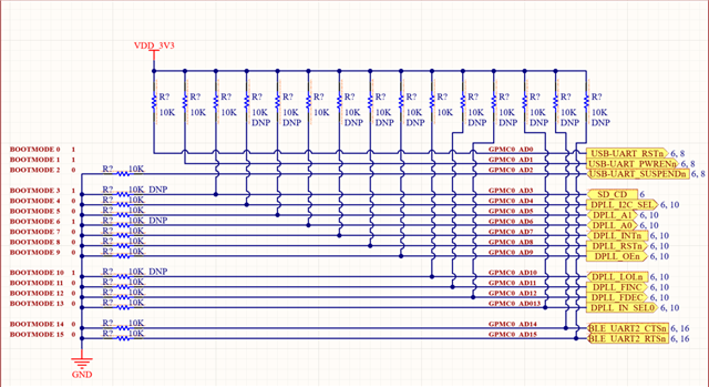
We are planning to use the AM625x in our custom design and have the boot mode defined by 10K PU/PD and the same pins will be used as GPIO for other peripherals.

The PU supply for the boot mode pins will be provided by 3.3V (that is enabled by the GPO2 pin of the PMIC TPS6521901RSMR). So, power architecture wise, it will be similar to the EVK.

In this case, will we still require to keep the Boot mode buffers or will it work fine without Buffer?

Let me know if any additional details are required.

Thanks & Regards,
Sahil Nayak

  • Hi Team,

    Do you have any updates to share?

  • Hello Sahil Nayak,

    The buffers are not a requirement, however, you need to ensure that no external peripheral is driving BOOTMODE pins during sampling time. This time is specified in the datasheet.

    One (pretty much obvious) measure is to use these pins as GPIOs in output direction only.

    It is not always possible, if so, then make sure to keep the external peripheral chips that are driving GPIOs are held in reset during sampling time. 

    If the above is also not possible, then custom gating circuitry like external buffers may be required.

    Regards,

    Stan

  • Hi Stan,

    Thank you for your response.

    Please see the attached image for the GPIOs connected to the boot mode pins:

    The only issue is with DPLL pins. It's the Network synchronizer that provides the 25MHz clock to the MCU_OSC0_XI pin of the AM62x. So, we cannot put the DPLL in the reset mode while the boot mode pins are latching. We cannot put a buffer for those pins since the DPLL needs to start before the MPU to provide the 25MHz clock to the MPU.

    Do you see any solution to mitigate the boot mode pins latching issue?


  • Hi Sahil,

    For USB-UART and BLE, typically these type of devices can be held in reset with the RESETSTATz SoC pin. This should make them inactive after MCU_PORz when the BOOTMODE pins are being latched.

    For DPLL, I'm not sure how the input (to SoC) pins are acting. You need to ensure they are not driven in the opposite to pulls direction. Best is they are not driven at all. Here is the case you may need additional gating/buffering. As a side note, check if there is a chance pins like INTn to be open-drain and require  pull-ups to operate.

    For SD card Card Detect, I'm afraid it's not possible to route it to BOOTMODE GPIO because it is never certain if the system starts with card inserted or card slot empty.

    Regards,

    Stan

  • Hi Stan,

    Thank you for your response.

    I believe the boot mode pins will be input during the booting sequence.

    What if I play a bit with pin muxing and use all the boot mode pins in output mode for external peripherals after boot? Will that work and eliminate the need for a buffer?

    Please note that in output mode, it may have PU/PD as per the external peripheral requirement.

  • Hello Sahil,

    Thank you for the inputs.

    Stan is currently out of office. Please expect his response early next week.

    Thanks

    Kind Regards,

    Anastas Yordanov

  • Hi Sahil,

    You can move all GPIO signals that are inputs to another GPIO pins that are non-BOOTMODE pins. This will eliminate the need of external buffer.

  • Hi Stan,

    Thank you for your confirmation.

    We will have all the GPIOs in output mode for the boot mode pins that may have external PU/PD. I hope that works to eliminate the external buffer.

  • Hi Sahil,

    Thanks for your prompt feedback.

    Regards,

    Anastas Yordanov