AM2732-Q1: Callback interrupt problem when using RCSS_SPIA as slave

Part Number: AM2732-Q1
Other Parts Discussed in Thread: AM2732, SYSCONFIG

Hello,

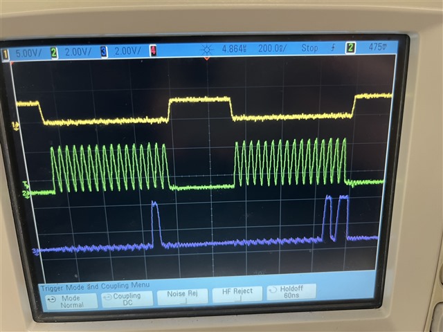
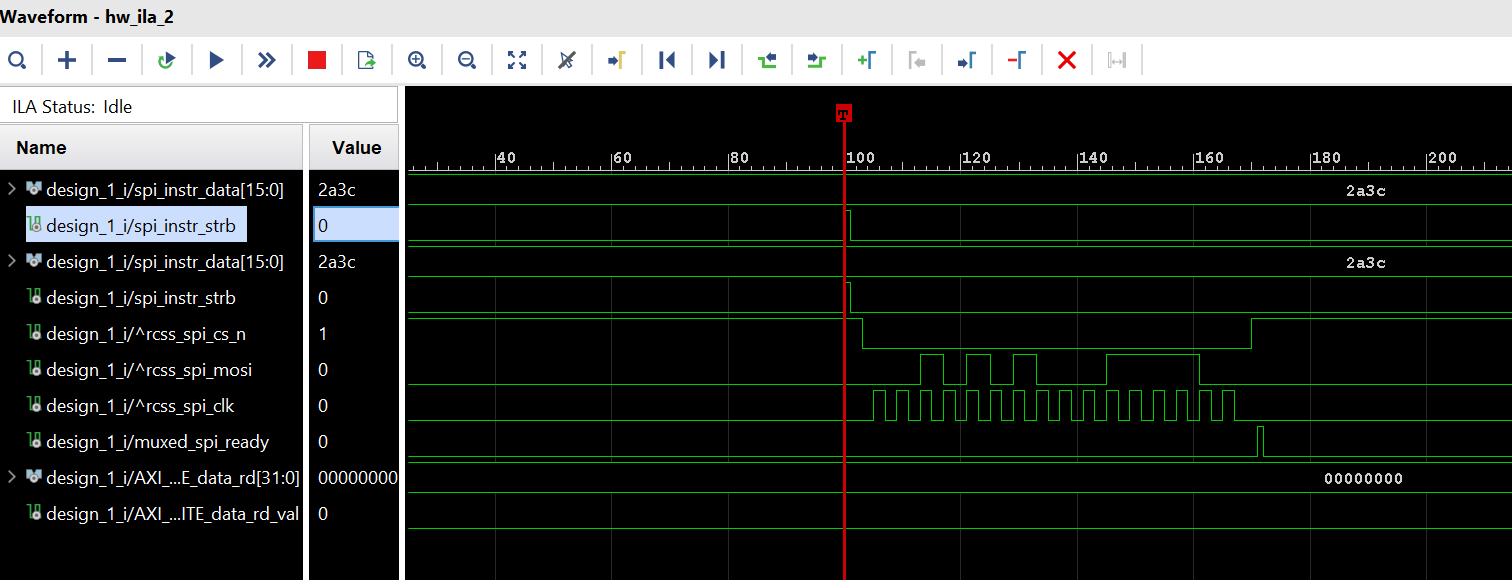
I use the RCSS_SPIA interface as slave in the AM2732 device. The AM2732 device is connected through j1 connector with a FPGA device that sends SPI master frame on RCSS every 10 ms (a simulations of the data send is shown below).

image.png

The problem is that in the AM2732 device I only get one interrupt in the beginning with the right data written in memory and then I do not get any more interrupts.
The syscfg and the code used is shown below.
image.png

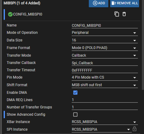
uint32_t intr_callback_cnt = 0;
uint16_t gMibspiRxBuffer[1];

void Spi_Callback(MIBSPI_Handle handle, MIBSPI_Transaction *transaction)
{
CacheP_wbInv(gMibspiRxBuffer, sizeof(gMibspiRxBuffer), CacheP_TYPE_ALLD);
intr_callback_cnt++;
if(intr_callback_cnt == 4){
     DebugP_log("4 spi transfers\r\n");
}
}

void spi_slave(void *args)
{
    //int32_t             status = SystemP_SUCCESS;
    uint32_t            i;
    int32_t             transferOK;
    MIBSPI_Transaction  spiTransaction;

    Drivers_open();
    Board_driversOpen();

    DebugP_log("[MIBSPI] Digital Loopback EDMA example started ...\r\n");

    /* Memfill buffers */
    for(i = 0U; i < sizeof(gMibspiRxBuffer); i++)
    {
        gMibspiRxBuffer[i] = 0U;
    }

    CacheP_wbInv(gMibspiRxBuffer, sizeof(gMibspiRxBuffer), CacheP_TYPE_ALLD);
    
    /* Initiate transfer */
    spiTransaction.count        = sizeof(gMibspiRxBuffer);
    spiTransaction.txBuf        = NULL;
    spiTransaction.rxBuf        = (void *)gMibspiRxBuffer;
    spiTransaction.peripheralIndex   = 0U;
    spiTransaction.arg          = NULL;
  

    transferOK = MIBSPI_transfer(gMibspiHandle[CONFIG_MIBSPI0], &spiTransaction);
    if((SystemP_SUCCESS != transferOK))
    {
        DebugP_assert(FALSE); /* MIBSPI transfer failed!! */
    }
    else
    {
        DebugP_log("All tests have passed!!\r\n");
    }


}

Can you tell me whats going wrong?

  • Hi Dimitra,

    Each MIBSPI_transfer() will correspond to one RX transaction (with spiTransaction.count data unit). In your code, you only do MIBSPI_transfer() once, so, there will be only one TX trancsaction and one TX callback.

    The MIBSPI_transfer() should be in a loop, so that the TX transactions will come in continuously.

    Best regards,

    Ming  

  • Hi Ming,

    I think this fixed my problem. I have one last question though.

    I changed the ending of my spi_slave() function to this:

        while(1){
        transferOK = MIBSPI_transfer(gMibspiHandle[CONFIG_MIBSPI0], &spiTransaction);
        if((SystemP_SUCCESS != transferOK))
        {
            DebugP_assert(FALSE); /* MIBSPI transfer failed!! */
        }
        else
        {
            //DebugP_log("All tests have passed!!\r\n");
        }
    
        ulEventsToProcess = ulTaskNotifyTake( pdFALSE, portMAX_DELAY );
        if (ulEventsToProcess > 1){
                ;
            }
        }
    And I also changed my Spi_callback function to this:
    // uint32_t startCycles;
    uint64_t curTime;
    float durationCallback[100];
    
    void Spi_Callback(MIBSPI_Handle handle, MIBSPI_Transaction *transaction)
    {
        if(intr_callback_cnt>0){
            durationCallback[(intr_callback_cnt-1)%100] = ClockP_getTimeUsec() - curTime;
            // durationCallback[(intr_callback_cnt-1)%100] = (CycleCounterP_getCount32() - startCycles - 15)*1000/400E6;
        }
    
        // startCycles = CycleCounterP_getCount32();
        curTime = ClockP_getTimeUsec();
    
        CacheP_wbInv(gMibspiRxBuffer, sizeof(gMibspiRxBuffer), CacheP_TYPE_ALLD);
        intr_callback_cnt++;
        BaseType_t TaskWoken = pdFALSE;
        vTaskNotifyGiveFromISR( gSPI_slave_Task, &TaskWoken );
        portYIELD_FROM_ISR( TaskWoken );
    }

    My problem now has to do with the time measurement.

    When I use ClockP_getTimeUsec(), I accurately measure the 10ms duration from one interrupt to another. When I use the CycleCounterP_getCount32() I always get around 78usec. Why is that huge difference between these 2 time measurement ways.

    Thank you in advance.

    Dimitra

  • Hi Dimitra,

    There is an know bug for the CycleCounterP_getCount32() on R5F core. The cycle count for R5F core is inaccurate. However, the CycleCounterP_getCount32 for C66x core is accurate. Please use other methods like GPIO pin toggle to measure the time between two interrupts. 

    Best regards,

    Ming

  • Hi Ming,

    Thank you for the information. I would like to ask for your help with another issue.

    I managed to get data from the FPGA. The FPGA sends a 16bit counter every 10us and what I do is modifying my code so that I get 256 packets of 16bit data and after the run I observe the content of the receiving buffer (gMibspiRxBuffer) in memory and I see that all the data is correct.

    The problem is that when the FPGA is sending 1024 packets every 10us , I get the data in the receiving buffer correctly but the first 5 packets are zero and the correct counter value starts from the 6th packet. 

    Do you know why that happens? I must also mention that in packet numbers over 1024, the same problem appears.

    Thank you in advance.

    Dimitra

  • Hi Dimitra,

    Since the AM273x is the SPI slave, I would think the issue is on the FPGA side which is the SPI master. 

    If you can connect the Saleae Logic Pro to the MIBSPI CS, CLK, MISO, MOSI, you should be able to get the log of the data sent by FPGA. If it matches with the RX buffer contents, then the issue is with the FPGA for sure.

    Best regards,

    Ming 

  • Hi Ming,

    I confirmed  that the data provided from the FPGA are correct. So the problem lies elsewhere.

    My receiving buffer is shown in the picture below when I receive 1024 packets every 10us. It is clearly shown that the first packets of the counter are not received with the right values, although the FPGA sends them correctly (that is verified). The rest of the packets (not the entire buffer is shown in this screenshot) are received correctly.

    Do you have an idea why that happens?

    Kind regards,

    Dimitra

  • Hi Dimitra,

    " although the FPGA sends them correctly (that is verified)"

    The verification you mentioned above is on the FPGA side or on the SPI bus connecting the FPGA and AM273x?

    From the screen capture of the gMibspiRxBuffer, it only says the AM273x received 6 empty packets, but what is the actual signal sending on the SPI bus is the key. The bottom line is AM273x is a SPI slave, it only gets what the SPI master (FPGA) sent. 

    If you can prove the SPI bus does have the first 6 packets with valid data, but AM273x get empty data, then the issue is on the AM273x side.

    If the first 6 packet are empty on the SPI bus, then the issue is on the FPGA.

    Please capture the SPI bus signals (CS, CLK, MOSI) using Saleae Logic Pro for the first 6 packets

    Best regards,

    Ming

  • Hello Ming,

    I verified with an oscilloscope the SPI bus. As you can see in the captures below the first 6 packets are not empty. 

    The green signal is the clock and the blue one MOSI. I verified also the CS but I had a problem with the 3rd probe and could not have all three signals together (verified that it works fine).

    Does that mean the issue is in the AM273x? Is there maybe something wrong in the AM273x configuration?

    Best regards,

    Dimitra

  • Hello again,

    I managed to get all SPI bus signals in the oscilloscope. In the pictures below are shown CS(yellow), CLK(green) and MOSI(purple).

    The picture below shows one part of the first data that were received in the same run where the oscilloscope pictures have been taken.

    The problem insists. Why does that happen?

    Best regards,

    Dimitra

  • Hi Ming,

    Do you have any news regarding my issue?

    Best regards,

    Dimitra

  • Hi Dimitra,

    Can you try to change the "Frame Format" (Mode 0/1/2/3 etc.):

    Best regards,

    Ming

  • Hello Ming,

    unfortunately nothing worked.

    Can you please confirm that my EDMA configurations are correct? Maybe the problem is there.

    These are the EDMA configs from my syscfg:

    Thank you in advance!

    Best regards,

    Dimitra

  • Hi Dimitra,

    Here are my syscfg settings for MIBSPI & EDMA:

    Note Region ID is Region 0 (yours is region 2)

    Best regards,

    Ming

  • Hi Ming,

    I tried your EDMA settings but that still didn't fix my issue.

    I forgot to mention that my project is based on FreeRTOS however I have no other running tasks of my own apart from the spi_slave task.

    Also my project is on R5 and not on DSP like yours.

    I have 3 questions for you:

    1) Is it a problem I am trying this on R5 and you are doing it on DSP?

    2) Why are you still using CCS 12.7 and not CCS 20.2 like I am? Could that be an issue?

    3) When I try to repeat my example but without DMA enabled (I keep the process exactly the same as before) I get an error that 

    MIBSPI_transfer failed. More specifically, I reach this part of code inside the mibspi_v0.c driver. Why is this happening?

    Best regards,

    Dimitra

  • Hi Dimitra,

    1) the R5F core seems cannot access to the RCSS_MIBSPIA or RCSS_MIBSPIB, at least the SysCFG does not allow that. Can you try it on C66x core?

    2) Using CCS 12.7.0 is just my preference. I do not think it causes any problem.

    3) According to the MIBSPI_transferCore() in mibspi_v0.c, if the Multi iCount support is not defined, the Callback mode is not supported. I do not know it is a limitation of the driver or the IP. Please use the EDMA at this time.

    Best regards,

    Ming

  • Hi Ming,

    1) Regarding RCSS_SPIA/RCSS_SPIB visibility from R5 cores, they are both visible in my syscconfig. Here is the attached screenshot proving it is available.


    2) I will use EDMA, but where do I have to look for the correct EDMA configurations? TRM does not have something clear and copying your settings in my project still didn't solve the problem.


    3) I also tried reproducing your setup with RCSS_SPIA on the C66 DSP using a system project. I tried both FreeRTOS/NORTOS and still nothing worked. Error occurs when I call the function MIBSPI_transfer. Specificaly, this is where it fails (with the use of eDMA).

    3) When I try to repeat my example but without DMA enabled (I keep the process exactly the same as before) I get an error that 

    MIBSPI_transfer failed. More specifically, I reach this part of code inside the mibspi_v0.c driver. Why is this happening?


    Furthermore, how did you run the DSP as a standalone project? As mentioned in this thread here it is not possible in NOBOOT mode. It has to be inside a system project, otherwise you have to be in QSPI mode where the initialization SBL binary are already flashed and will run as soon as the EVM is powered on. Are you on QSPI mode or on NOBOOT mode?


    4) I will briefly explain my SPI test once again to make sure we are aligned.

    - My FPGA design has an unsigned 16-bit counter that goes from 0 to 65535. The FPGA sends 16-bit data every 10us.

    - Every time the FPGA transmits 16 bits that hold the value of the counter (as also shown in my previous posts with the captures form the oscilloscope). So basically at "SPI transfer #0" I receive the value 0 at my AM2732, at "SPI transfer #1" I receive the value 1 at my AM2732 and so on and so forth as the counter increments.


    My problem is the following. I am using callback mode and the AM2732 is in peripheral (slave) mode. When I set a receiving buffer size over 128 words  (uint16_t gMibspiRxBuffer[SIZE]) it never fully works properly.


    I noticed the driver handles the exact 128-word RAM limit with remainSize = dataLength % ramSize — it splits transfers into128-word chunks + remainder automatically.

    THE FACT IS THAT : driver splits >128 word transfers into two phases: first 128 words (DMA callback as selected in sysconfig), then remainder (blocking SemaphoreP_pend).

    SO I ASSUME: My 129-word test fails because the FPGA bursts all 129 packets in 1.29ms (10µs each), but the driver's 2nd blocking transfer can't keep up.

    below there is a screenshot with the data I receive running this test:

    It seems that packet 129 that should hold the value 128, was not received. Instead it was received a  packet that was transmitter later.

    So my Questions are:

    - Can I modify the code so that the second phase is not BLOCKING but instead NON BLOCKING?

    - Are my transfers with in-between delay 10us too fast? Is there a limit to that I should know? 

    - How should I handle this problem in order to receive bigger Buffers but with all correct data and with non blocking features?

    Best regards,

    Dimitra

  • Hi Dimitra,

    Ming is out of the office on personal leave until the 23rd, in the meantime I will try to help you with what I can.

    Furthermore, how did you run the DSP as a standalone project? As mentioned in this thread here it is not possible in NOBOOT mode. It has to be inside a system project, otherwise you have to be in QSPI mode where the initialization SBL binary are already flashed and will run as soon as the EVM is powered on. Are you on QSPI mode or on NOBOOT mode?

    This is not necessarily true. Like mentioned at the end of that thread, you would need to make sure that the target configuration that you are launching is also running the GEL files configuration. GELs are just initialization scripts, included in the CCS installation, that can be associated with device data to run automatically upon launching a target config for debugging. If using the NO BOOT mode you have to make sure that the target config you are using has a path on the initialization scripts box. If you are unsure if you have this then double click your target config file and share with me the open window, you should be able to see something similar to this

    I understand the transfer you are trying to make. Have you checked the mibspi registers as you receive the incorrect data for any exception flags? It would be helpful in telling the state of the controller at the given moment. 

    can you capture the mmrs when: you receive the erroneous 0's on the first couple packet transfers, when you receive your 128th transfer, and when you receive your 129th transfer.

    Also, can you confirm at what speed are you running the SPI peripheral? have you tried lowering the clock speed? 

    Best,

    Daniel

  • Hi Dimitra,

    Sounds like you are using the Multiple buffer mode of the MIBSPI which can have up to 128 buffers. Can you try to use the "Compatibility Mode" which compatible with the standard SPI mode:


    Best regards,

    Ming

  • Hi,


    I tried turning the Compatibility Mode On in sysconfig, but it didn't solve my problem.

    I still have the same problem. Can you give me a working SPI example code with your hardware that will demonstrate the usage of SPI, instead of just citing the loopback example inside the SDK.

    Best regards,

    Dimitra

  • Hi Dimitra,

    Attached please find the MIBSPI slave and master examples I used on AM273x EVMs. The only difference is the MIBSPI data size is 8-bit instead of 16-bit. I used two AM275x EVMs. One as SPI master and one as SPI slave. They worked as expected. The examples are based on the AM273x FreeRTOS SDK 09.02.00.60

    mibspi_loopback_am273x-evm_r5fss0-0_nortos_ti-arm-clang.zip(SPI slave)

    mibspi_loopback_am273x-evm_r5fss0-0_freertos_ti-arm-clang.zip(SPI master)

    Best regards,

    Ming

  • Hi Ming,


    ->What you are doing in your MASTER-SLAVE example is completely different than our case. You can see the differences below.

    1) You have DMA disabled. (You instructed us to keep it enabled.)

    2) You are doing 8-bit transfers while we are doing 16-bit transfers.

    3) You are transmitting only 64 bytes while we are transmitting a total of 1024 bytes (512 x 16-bits).

    4) You are using FreeRTOS on the MASTER and NORTOS on the SLAVE, while our SLAVE is in FreeRTOS.

    5) You are not using callback functions. You only have blocking mode.

    6) You are using Compatibility Mode. We are not.

    7) At your MASTER sysconfig we noticed that you have CS Hold Enable. While our FPGA only drops the CS to low every time it transmits 16bits. Does that option mean that YOU keep the CS low for the whole transmission of 64*8-bits?

    Please try to reproduce our example from one Sitara to another and let us know about your results.


    ->Another finding we made is that when we change place of the CacheP_wbInv() function, that previously was inside the Callback function and put it as shown in the code below, all the data appear to have been received correctly.

    With what interrupt is the Callback triggered? Does the Callback get triggered before the DMA transfer has been completed? Why does the change of the CacheP_wbInv() function appear to impact the result?

    #include "spi_dma_callback.h"
    #include <kernel/dpl/ClockP.h>
    #include <drivers/mibspi.h>
    
    TaskHandle_t gSPI_slave_Task = NULL;
    #define SPI_SLAVE_TASK_SIZE (2*256)
    
    #define SPI_TRANSFER_SIZE (1024)    // SPI transfer size in bytes
    
    uint16_t gMibspiRxBuffer[SPI_TRANSFER_SIZE/2];
    
    int32_t SPI_createtasks(void)
    {
        xTaskCreate(spi_slave, "SPI_slave", SPI_SLAVE_TASK_SIZE, NULL, SPI_SLAVE_TASK_PRI, &gSPI_slave_Task);  
        if(gSPI_slave_Task != NULL)
     {
      return SystemP_SUCCESS;
     }
     else
     {
      return SystemP_FAILURE;
     }
    }
    
    
    void Spi_Callback(MIBSPI_Handle handle, MIBSPI_Transaction *transaction)
    {
        BaseType_t TaskWoken = pdFALSE;
        vTaskNotifyGiveFromISR(gSPI_slave_Task, &TaskWoken);
        portYIELD_FROM_ISR(TaskWoken);
    }
    
    
    void spi_slave(void *args)
    {
        int32_t transferOK;
        MIBSPI_Transaction spiTransaction;
        uint32_t ulEventsToProcess;
    
        Drivers_open();
        Board_driversOpen();
    
        memset(gMibspiRxBuffer, 0xFF, SPI_TRANSFER_SIZE);
    
        spiTransaction.count = SPI_TRANSFER_SIZE;
        spiTransaction.txBuf = NULL;
        spiTransaction.rxBuf = (void *)gMibspiRxBuffer;
        spiTransaction.peripheralIndex = 0U;
        spiTransaction.arg = NULL;
    
        while(1){
            transferOK = MIBSPI_transfer(gMibspiHandle[CONFIG_MIBSPI0], &spiTransaction);
            if(SystemP_SUCCESS != transferOK)
            {
                DebugP_assert(FALSE); /* MIBSPI transfer failed!! */
            }
    
            ulEventsToProcess = ulTaskNotifyTake(pdFALSE, portMAX_DELAY);
    
            CacheP_inv(gMibspiRxBuffer, SPI_TRANSFER_SIZE, CacheP_TYPE_ALLD); // also seems to work with CacheP_wbInv
    
            if (ulEventsToProcess > 1){ ; }
        }
    }
     

    Best regards,

    Dimitra

  • Hi Dimitra,

    First of all, I am travelling right now. I do not the HW setup to test your user case on AM273x EVMs. I will be back to office on 2/24/2026. 

    It also seems that you have a working solution for your problem.

    To answer your questions regarding to the MIBSPI RX callback function:

    1. The callback function is called by the MIBSPI ISR,

    2. It is possible that the last DMA has been submitted but completed yet.

    3. The way you use the CacheP_inv() or CacheP_wbInv() in the above code is correct. You should not call them in the callback function based on the 1-2

    Best regards,

    Ming

  • Hi Dimitra,

    Did my previous answers help you or not? If it does not resolve your issue, please reply to this thread. Only click the rejection button does not help the debug process. If it does resolve your issue, can I close this thread?

    Best regards,

    Ming

  • Hi Ming,

    you can close the thread yes.

    Best regards,

    Dimitra