This thread has been locked.

If you have a related question, please click the "Ask a related question" button in the top right corner. The newly created question will be automatically linked to this question.

AM3352: MMC1 with GPMC together

Part Number: AM3352
Other Parts Discussed in Thread: SYSCONFIG,

4GB eMMC is harder to buy now, more start from 8GB, so must use eMMC1 port to boot.

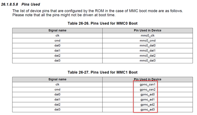
There is a notes on TRM, GPMC is not usable with eMMC1 due to pinmux options. 

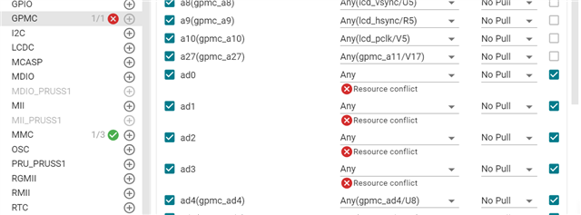
Buf configure eMMC1 in 4bit mode and 16bit GPMC in sysconfig, there is no conflication.

I think 4bit eMMC1(booting device) and 16bit GPMC can be used together. please double confirm.

image.png


image.png

  • Hello Tony,

    Thank you for the query.

    You may also wish to refer to this AM3352 thread:

    4-bit eMMC operations support by AM3352

    where ROM booting in 4-bit eMMC confirmed. Therefore 4-bit eMMC operations on the MMC1 port are verified for Read transfers up to ~5 MBytes/sec (10 MHz and 4-bit mode, excluding command/response overhead).

    It can be seen from the Pinmuxing tables in the AM335x Datasheet that the following I/O Set of MMC1 pins satisfies the condition for having the GPMC and MMC1 interfaces co-existing/operating on the board without any conflict.

    Let's prove this:


    The SoC MII1 interface pins  are thus the only I/O Set of pins which satisfy the condition to have the 4-bit MMC1 signals not conflicting with the GPMC signals. There are no GPMC signals multiplexed on these pins. 

    The customer can even use a <4 GB sized eMMC card on the SDMMC0 port for non-boot purposes in 8-bit eMMC mode (achieving better transfer speeds), if the GPMC interface usage is restricted to 16-bit addressing / 16-bit data multiplexed mode. In this case the MMC0_DAT0... MMC0_DAT7 are in an I/O set which does not conflict with the GPMC_AD0-GPMC_AD15 signals.    

    I am NOT sure why is the NOTE: "If MMC1 is used, the GPMC is NOT usable, due to pin muxing options." present in the AM335x TRM. Could it be because of some eMMC interface timing parameter violations. On the other side, there is No such restriction note to be found in the AM335x Datasheet. 

    I will doublecheck this with the responsible AM335x pinmux expert and let you know. Please expect that some delay is possible.

    Thanks

    Best Regards

    Anastas Yordanov 

  • Hi Anastas,

    Is there update?

  • Hi Tony,

    I apologize for I have incidentally omitted to request per email a confirmation from the AM335x pinmux expert.

    But I actually found the E2E thread that answers your question, why there is the TRM NOTE specifying:

     "If MMC1 is used, the GPMC is NOT usable, due to pin muxing options."

     AM335x: Using GPMC, MMC1 and MMC0

    I am sending your request for confirmation to the AM335x Pinmux expert now.

    Thanks

    Kind Regards

    Anastas Yordanov

  • I got it. 

    MMC1 boot pin used table shows it is fixed pins. if set MMC1 use below pins in sysconfig, GPMC is conflicted on AD0-3 

  • I am thinking if boot SPL by ROM, then configure eMMC PINMUX to IOSet_1 as below which can coexist with GPMC. Add a 2:1 bus switch to select the right signal from SOC to eMMC device in different stage.

    Sounds doable, how do you think?

  • Hi Tony,

    Thanks for the thoughts.

    I am thinking if boot SPL by ROM, then configure eMMC PINMUX to IOSet_1 as below which can coexist with GPMC.

    I see a contradiction with what the example thread states. Can you clarify ? "

    In order to boot from MMC1, you will need to change the pinmux configuration to use the IO Set 1 instead of IO Set 2. This will disable the use of GPMC0 even with 8-bit data."

    Q1. Help me understand, what is the idea: Do you prefer to boot from >=4 GB sized EMMC in the AM3352 ROM stage or in the SBL stage ? 

    Q2. Do you need to preserve the GPMC boot functionality in the ROM boot phase ?

    Thanks

    Best Regards,

    Anastas Yordanov

  • Tony, i'm also confused here.  The original question mentions that only >4GB memories are available.  So they must use MMC1 port to boot out of ROM.  This precludes the use of GPMC, as you showed in the pinmux tool.  Seems convoluted to switch to MMC0 in the SPL stage and use a mux on board.  Is that what you are suggesting?  

    Regards,

    James

  • Q1. Help me understand, what is the idea: Do you prefer to boot from >=4 GB sized EMMC in the AM3352 ROM stage or in the SBL stage ? 

    ROM Stage:  eMMC1 boot with IO Set2.

    SBL Stage: switch eMMC1 to IO Set1. then eMMC1 can coexist with GPMC which connect to GPMC.

    No need GPMC boot, need GPMC functionality for application.

    Draw a simple block diagram as below:

  • Hi Tony,

    Thanks for the block diagram illustration of your idea. I think it is now clear. 

    I only have one notice - you maybe swapped the IO SET1 with IO SET2. Once again the excerpt from the example thread:

    As far as I understand:

    After POR, the hardware IO Mux will be setup (for example, some GPIO reset value) to select the MMCSD1 signals on the "IO Set1 pins" before ROM boot stage and will ensure the 4-bit eMMC1 booting on the ROM code expected pins. At the same time the Switch will detach the GPMC I/Os from the same IOSet1 pins to avoid contentions with eMMC1 during ROM booting.

    When SPL is loaded and  SPL boot stage is started, the SPL will update the IO Mux, thus re-mapping the eMMC1 interface to the IO Set2 SoC pins where the eMMC1 memory will be further-on accessible by the software in the remaining lifetime stages. The SPL will also re-map through the Switch the GPMC AD0-AD7 signals to the IOSet1, making GPMC available for a 8-bit FPGA interfacing during App lifetime.

    Best Regards

    Anastas

  • Hi,

    deleted my unintentionally repeated post !

    Thanks

    Best Regards

    Anastas

  • Hi Tony,

    This has been marked as resolved, so I am closing it.

    Please open a new thread if you have further questions.

    Thanks

    Best Regards

    Anastas Yordanov