This thread has been locked.

If you have a related question, please click the "Ask a related question" button in the top right corner. The newly created question will be automatically linked to this question.

AM6442: AM6442 internal PCIe REFCLK jitter issue

Part Number: AM6442

Hi Team ,

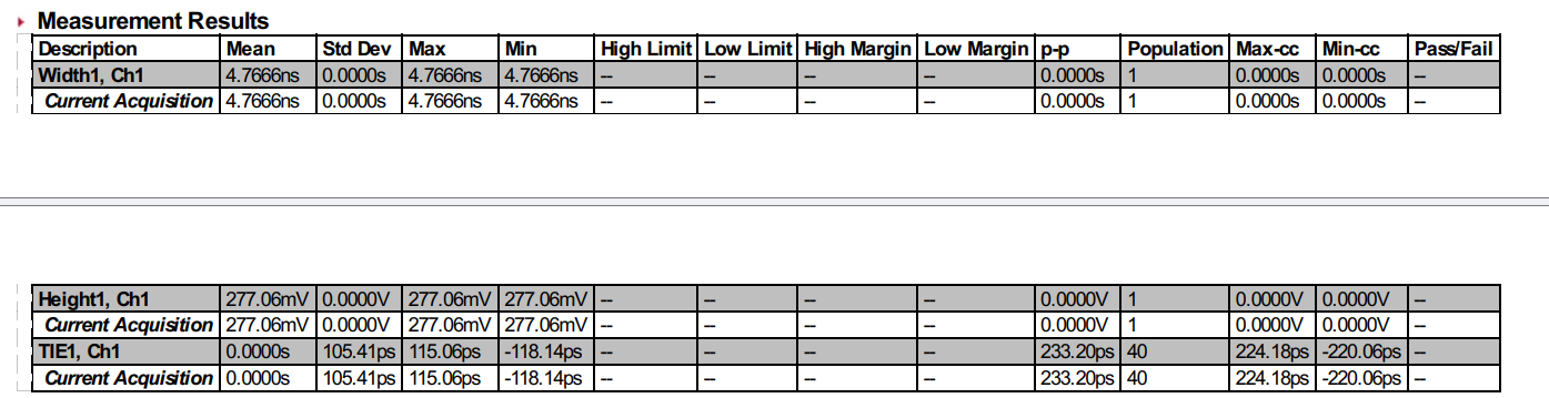
We are facing jitter related issue in internal PCIe reference clock in our custom AM64 board , And observe clock signal quality is not good. We observed that in AM6442 (Silicon Rev 2.0) ERRATA document has metioned issue related to this (i2241,i2326 ) . Is there a way to improove the internal PCIe reference clock to comply with PCIe standard , If yes kindly provide the inputs on how to proceed further. Attached scopeshots for the reference. image.png
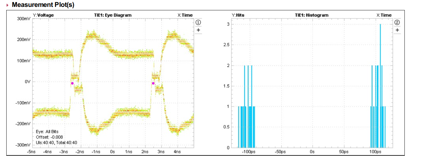
image.png

  • Hello Aditya Patil, 

    Please refer inputs i received from the devoice expert:

    It appears the signal was captured at about 2 inches from the far end of the signal path based on the mid-supply step observed on the waveform.  They need to capture the signal at the far end of the signal trace to eliminate the mid-supply step.

     The signal also appears to be over-driven, which could be improved by placing a series termination resistor near the source.

    Is there a series resistor provision provided for the clock output ?

    Regards,

    Sreenivasa

  • Hi Kallikuppa sreenivasa , 

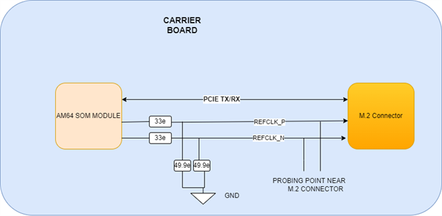
    We probed the signal with differential probes solderes on vias near the M.2 connector where we interfaced the PCie SSD card . We have placed 33 ohm series resistor near the AM64 SOM . To experiment we replaced 33 ohm to 0 ohm and removed 49 ohm resistor and observe improovement in the REFCLK. Please refer the attached images .Kindly let us know how to proceed further

    NOTE : scopeshot attached is in 0 ohm series resistor and  49.9 ohm resistor demounted


  • Greetings Aditya,

    Probing the signal like this can still introduce reflections that may interfere with any scope based validation or scope software package (like a PCIe validation package). Getting even closer the SSD would be better for an accurate picture, as the mid-supply step still appears to be due to a reflection on where it was probed. 

    The best possible probe point would be a replacing with the SSD with some sort of M.2 PCIe compliance fixture that allows for the most accurate representation of the signals. The typical PCIe connector has compliance load boards made by PCIe-SIG for this exact scenario, testing a custom board with an RC. These boards have also have 2.92 mm connectors that help reduce the probing itself distorting the signal, but would require your scope to support this or have cabling to interface to adapt it.

    Sincerely,

    Lucas

  • Hi Lucas,

    Please refer to the attached documentation for the PCIe REFCLK probing location. The physical distance between the probe points (vias) and the M.2 connector pins is approximately 11.39mm. Despite the close proximity to the connector do you anticipate that the probe loading or the resulting stub will significantly impact signal integrity via reflections, or is the electrical length short enough to be considered negligible in this test setup?

  • Greetings Aditya,

    Is the M.2 connector and SSD board populated in this probing setup? In addition to the stubs+probing I think the physical connector itself and device+PCB may add to any reflections as well. Something closer to ideal would likely be desoldering the M.2 connector and trying to probe at the pad itself (if it's even logistically possible), you may have the probe loading but should see less reflections from any stubs or the device/connector impedances.

    Probing at the end of the transmission line with some compliance load board is still probably the most accurate method of seeing the true reference clock the endpoint device will see, as it'd also likely have a high speed connector to minimize any distortion from the probing (like a 2.92 mm connector meant for high speed signal verification). It's also in line with the PCIe REFCLK test setup section, which the REFCLK A/C specifications are tested to. The excerpt in question is: "Note that the Refclk signal is tested into a load that represents the series (open) termination appearing at the Refclk input pins of a PCIE device." (PCI Express Rev 4.0 Section 8.6.1 Refclk Test Setup)

    Sincerely,

    Lucas