This thread has been locked.

If you have a related question, please click the "Ask a related question" button in the top right corner. The newly created question will be automatically linked to this question.

AM62P: AM62Px DSS DPI (RGB parallel) support in Linux / tidss

Part Number: AM62P

Hello TI Support,

I am working with AM62Pxx (AM62Px EVM) using Linux (tidss / DRM). I am trying to output RGB parallel (DPI) display from DSS.

My device tree connects a panel-dpi to DSS port, and the panel is correctly probed,

but tidss always fails with: tidss 30220000.dss: unsupported vp_bus_type 2

This happens on all DSS ports (port 0 and port 1).

-------------------------------------------------------------------------------------------

[    0.075079] /bus@f0000/dss@30220000: Fixed dependency cycle(s) with /panel
[    0.075157] /panel: Fixed dependency cycle(s) with /bus@f0000/dss@30220000
[    0.305852] tidss 30220000.dss: TIDSS DEBUG: start probing port 0
[    0.305878] tidss 30220000.dss: TIDSS DEBUG: port 0 -> panel=000000002146ea68 bridge=0000000000000000
[    0.305886] tidss 30220000.dss: TIDSS DEBUG: setting up panel for port 0
[    0.305934] tidss 30220000.dss: TIDSS DEBUG: unsupported vp_bus_type 2 for port 0
[    0.305940] tidss 30220000.dss: failed to init DRM/KMS (-22)
[    0.306166] tidss 30220000.dss: probe with driver tidss failed with error -22

root@am62pxx-evm:~# dmesg | grep dss
[    0.074061] /bus@f0000/dss@30220000: Fixed dependency cycle(s) with /panel
[    0.074142] /panel: Fixed dependency cycle(s) with /bus@f0000/dss@30220000
[    0.305653] tidss 30220000.dss: TIDSS DEBUG: start probing port 0
[    0.305675] tidss 30220000.dss: TIDSS DEBUG: port 0 -> no panel/bridge (ENODEV)
[    0.305680] tidss 30220000.dss: TIDSS DEBUG: start probing port 1
[    0.305693] tidss 30220000.dss: TIDSS DEBUG: port 1 -> panel=00000000345fe045 bridge=0000000000000000
[    0.305701] tidss 30220000.dss: TIDSS DEBUG: setting up panel for port 1
[    0.305706] tidss 30220000.dss: TIDSS DEBUG: unsupported vp_bus_type 2 for port 1
[    0.305712] tidss 30220000.dss: failed to init DRM/KMS (-22)
[    0.306058] tidss 30220000.dss: probe with driver tidss failed with error -22

-------------------------------------------------------------------------------------------

Question: Does AM62Pxx DSS support RGB parallel (DPI) output in Linux?

If not, is this a hardware limitation of AM62Pxx, or a software limitation of the current BSP / tidss driver?

If DPI is not supported, what is the recommended way to drive an RGB panel from AM62Pxx? (OLDI/LVDS + external bridge?)

Environment: - SoC: AM62Pxx - Board: AM62Px EVM - Linux: (kernel version / TI SDK version) - Display driver: tidss (DRM) 

Best regards, 

Fumiyuki Izawa

  • Hi Fumiyuki,
    Seems like you are trying to enable DPI output from DSS1 instead of the default DSS0.

    Check the below image for internal SoC routing:

    For enabling DPI output using DSS0VP1, please refer to the following E2E for an example:  AM623: DSS: DPI display on am62x 

    For enabling DPI output on DSS1VP0, along with the above patch modified for DSS1VP0, you'll also need to change the first DISPC_VP_INTERNAL to DISPC_VP_DPI in https://git.ti.com/cgit/ti-linux-kernel/ti-linux-kernel/tree/drivers/gpu/drm/tidss/tidss_dispc.c?h=ti-linux-6.12.y#n496 and also make sure that mux 241 and 245 are set correctly in your dts. 

  • Hello TI Support Team,

    We are working with an AM62Px EVM and trying to bring up a DPI LCD panel (320x240).
    After updating the DTS, the bus-type related errors are gone and the DSS/DRM driver initializes correctly, but the display remains completely black (no visible video output).

    Below are the details of our current status and investigation results.

    Environment
    SoC: AM62Px
    Interface: DSS → DPI panel
    Resolution: 320x240
    Pixel clock: 6 MHz
    Bus format: RGB888 (24-bit)

    dmesg output (excerpt)

    root@am62pxx-evm:~# dmesg | grep dss
    [ 0.072166] /bus@f0000/dss@30220000: Fixed dependency cycle(s) with /panel
    [ 0.072237] /panel: Fixed dependency cycle(s) with /bus@f0000/dss@30220000
    [ 0.304202] tidss 30220000.dss: TIDSS DEBUG: start probing port 0
    [ 0.304227] tidss 30220000.dss: TIDSS DEBUG: port 0 -> panel=00000000635506fb bridge=0000000000000000
    [ 0.304236] tidss 30220000.dss: TIDSS DEBUG: setting up panel for port 0
    [ 0.304241] tidss 30220000.dss: TIDSS DEBUG: port 0 connector_type panel=17 expected=17
    [ 0.304252] tidss 30220000.dss: TIDSS DEBUG: panel bridge created for port 0
    [ 0.304257] tidss 30220000.dss: TIDSS DEBUG: port 0 successfully added
    [ 0.304262] tidss 30220000.dss: TIDSS DEBUG: start probing port 1
    [ 0.304268] tidss 30220000.dss: TIDSS DEBUG: port 1 -> no panel/bridge (ENODEV)
    [ 0.305151] [drm] Initialized tidss 1.0.0 for 30220000.dss on minor 0
    [ 1.869951] tidss 30220000.dss: [drm] fb0: tidssdrmfb frame buffer device

    DRM and framebuffer (/dev/fb0) are created successfully.

    DRM / framebuffer check

    root@am62pxx-evm:~# cat /sys/class/drm/card0-*/modes
    320x240

    Writing random data to fb0:

    cat /dev/urandom > /dev/fb0
    cat: write error: No space left on device

    (This seems expected due to framebuffer size.)

    Backlight control

    root@am62pxx-evm:~# ls /sys/class/backlight/
    1-0036
    
    root@am62pxx-evm:~# cat /sys/class/backlight/1-0036/max_brightness
    255

    Brightness control works:

    echo 0 > /sys/class/backlight/1-0036/brightness
    echo 255 > /sys/class/backlight/1-0036/brightness

    Direct I2C access fails because the device is busy (controlled by the backlight driver):

    i2cset -y 1 0x36 0x11 0x11
    Error: Could not set address to 0x36: Device or resource busy

    DTS excerpt (panel and DSS configuration)

    panel_lcd: panel {
    compatible = "panel-dpi";
    status = "okay";
    
    backlight = <&backlight>;
    bus-format = <0x1017>; /* RGB888_1X24 */
    bus-flags = <0x6>;
    bpc = <8>;
    
    panel-timing {
    clock-frequency = <6000000>; /* 6 MHz */
    
    hactive = <320>;
    hfront-porch = <8>;
    hback-porch = <43>;
    hsync-len = <4>;
    
    vactive = <240>;
    vfront-porch = <8>;
    vback-porch = <12>;
    vsync-len = <4>;
    
    de-active = <1>;
    hsync-active = <0>;
    vsync-active = <0>;
    pixelclk-active = <1>;
    };
    
    port {
    panel_in: endpoint {
    reg = <0>;
    remote-endpoint = <&dss1_vp2_out>;
    };
    };
    };
    
    &dss1 {
    status = "okay";
    pinctrl-names = "default";
    pinctrl-0 = <&main_dpi_pins_default>;
    };
    
    &dss1_ports {
    port@0 {
    reg = <0>;
    dss1_vp2_out: endpoint {
    reg = <0>;
    remote-endpoint = <&panel_in>;
    bus-type = <2>; /* DPI */
    bus-format = <0x1017>;
    bus-flags = <0x6>;
    data-lines = <24>;
    };
    };
    };

    After this change, the bus-type related errors disappeared.

    Current issue
    DRM, DSS, and framebuffer are initialized correctly.
    Backlight can be controlled and turns on/off.
    Correct mode (320x240) is reported.
    However, no image is displayed on the panel (black screen).
    Questions / request for advice
    At this point, we believe further investigation is required.
    Could you please advise what aspects we should focus on next? For example:

    DSS VP (VP1/VP2) routing or port selection correctness
    DPI signal polarity (DE/HSYNC/VSYNC/PCLK) and whether additional inversion is required
    Pixel clock source and clock enable status
    Whether additional DSS or VP configuration is required for DPI panels on AM62Px
    Any known limitations or common pitfalls for DPI bring-up on AM62Px
    Any guidance on recommended debug steps would be greatly appreciated.

    Best regards,
    Fumiyuki Izawa

  • Hi Fumiyaki,
    Seems you missed a few configurations as per my last post.
    A few pointers / questions:
    1. What was the dts change that helped? Did you not need to do the driver change for DISPC_VP_INTERNAL?
    2. Are you trying to use DSS0VP1 or DSS1VP0. If using DSS1VP0, may I know if there is any specific reason?
    3. From your dts, looks like you are tring to use DSS1VP0 (since you used port@0 but labelled it as dss1_vp2_out). If you really want to use DSS1VP0, you will need to change mux values for MUX241 and MUX245 as mentioned earlier. To know how to change this, refer to &dss1 node example in this AppNote section.

  • Hi,

    Thank you for your comments.

    1. Yes, source code modification was required. The change related to DISPC_VP_INTERNAL was effective, and the bus type error is now resolved. Thank you for your guidance.

    2. I am using DSS1VP0. DSS0 is currently disabled because it is planned to be used for a separate HDMI output path in the future, but it is not in use at the moment.

    3. You are right about the label mismatch in the DTS. I apologize for that — it was a leftover label that I forgot to update.
    Regarding the MUX241 and MUX245 settings: I had not changed these values initially, because after applying the fix mentioned in point 1, the bus type error disappeared even without modifying the mux values.
    However, I now understand that changing the MUX241 and MUX245 values is still required when using DSS1VP0. I will re-check and update these settings accordingly, and I will follow up if I have any further questions.

    At the moment, the system is in the following state:
    - DRM device is created correctly.
    - Connector DPI-1 is detected and reported as “connected”.
    - A valid mode (320x240) is listed.
    - Backlight control is working.

    However, the display output remains completely black.

    Below are the relevant DRM debug logs and sysfs information for reference.

    DRM state:
    --------------------------------

    cat /sys/kernel/debug/dri/0/state
    
    plane[32]: plane-0
    crtc=(null)
    fb=0
    crtc-pos=0x0+0+0
    src-pos=0.000000x0.000000+0.000000+0.000000
    rotation=1
    normalized-zpos=0
    color-encoding=ITU-R BT.601 YCbCr
    color-range=YCbCr full range
    color_mgmt_changed=0
    
    plane[42]: plane-1
    crtc=(null)
    fb=0
    crtc-pos=0x0+0+0
    src-pos=0.000000x0.000000+0.000000+0.000000
    rotation=1
    normalized-zpos=1
    color-encoding=ITU-R BT.601 YCbCr
    color-range=YCbCr full range
    color_mgmt_changed=0
    
    crtc[39]: crtc-0
    enable=0
    active=0
    plane_mask=0
    connector_mask=0
    encoder_mask=0
    mode: "": 0 0 0 0 0 0 0 0 0 0 0x0 0x0
    
    connector[41]: DPI-1
    crtc=(null)


    --------------------------------

    sysfs DRM information:
    --------------------------------

    /sys/class/drm:
    card0
    card0-DPI-1
    
    /sys/class/drm/card0/card0-DPI-1/status:
    connected
    
    /sys/class/drm/card0/card0-DPI-1/modes:
    320x240


    --------------------------------

    From the DRM state, it appears that the CRTC is not enabled and no plane is currently attached to it, even though the connector is connected and a valid mode is present.

    Please let me know if there are any additional DSS1VP0-specific configurations that I should verify.

    Best regards,
    Fumiyuki Izawa

  • Hi Fumiyuki,
    Would request you to please use code blocks while pasting logs/code in your future replies.

    I am using DSS1VP0. DSS0 is currently disabled because it is planned to be used for a separate HDMI output path in the future, but it is not in use at the moment.

    Understood. A word of caution: Since DPI output would then be used by DSS1, to drive HDMI from DSS0, you'll need a separate OLDI to HDMI bridge on your board.

    I now understand that changing the MUX241 and MUX245 values is still required when using DSS1VP0. I will re-check and update these settings accordingly, and I will follow up if I have any further questions.

    However, the display output remains completely black.

    The black output is expected since by default MUX 245 is set to output DSS0VP1.

    Will wait for your results. For MUX 241, you can cross check your configuration using 'k3conf dump clock 241'

  • Hi,

    Thank you for your guidance.

    I am planning to update the DTS as shown below by adding the MUX241 (front) and MUX245 (back) configuration for DSS1VP0.

    <pre><code>
    &dss1 {
     status = "okay";

     /* DSS1 VP0 (front MUX) and DPI (back MUX) */
     assigned-clocks = <&k3_clks 241 0>, /* MUX241: DSS1 VP0 */
     <&k3_clks 245 0>; /* MUX245: DPI */

     /* PLL17 -> DSS1 VP0 -> DPI */
     assigned-clock-parents = <&k3_clks 17 0>, /* PLL17 */
     <&k3_clks 241 1>; /* DSS1 VP0 output */

     pinctrl-names = "default";
     pinctrl-0 = <&main_dpi_pins_default>;
    };

    /* DSS1 VP0 port definition */
    &dss1_ports {
     port@0 { /* DSS1 VP0 (DPI) */
      reg = <0>;

      dss1_vp0_out: endpoint {
        remote-endpoint = <&panel_in>;
        bus-type = <2>; /* DPI */
        bus-format = <0x1017>;
        bus-flags = <0x6>;
        data-lines = <24>;
      };
     };
    };
    </code></pre>

    At the moment, both k3conf and modetest are not installed on the target, so I am not able to dump the clock configuration yet.

    <pre><code>
    root@am62pxx-evm:/sys/class/drm/card0/card0-DPI-1# k3conf dump clock 241
    -sh: k3conf: command not found

    root@am62pxx-evm:/sys/class/drm/card0/card0-DPI-1# k3conf dump clock 245
    -sh: k3conf: command not found
    </code></pre>

    I will first apply the above DTS changes and verify the behavior after reboot.
    Once I see the result, I will follow up with the updated status.

    Please let me know if the above DTS configuration looks correct, especially the PLL17 clock ID usage.

    Best regards,
    Fumiyuki Izawa

  • Hi,
    Following is a reference on how to add a code block on E2E forum:

    /* DSS1 VP0 (front MUX) and DPI (back MUX) */
     assigned-clocks = <&k3_clks 241 0>, /* MUX241: DSS1 VP0 */
     <&k3_clks 245 0>; /* MUX245: DPI */

     /* PLL17 -> DSS1 VP0 -> DPI */
     assigned-clock-parents = <&k3_clks 17 0>, /* PLL17 */
     <&k3_clks 241 1>; /* DSS1 VP0 output */

    Seems incorrect:
    1. ordering has to be the same between clock and it parent.
    2. <241 0> will need <241 2> parent and similarly <245 0> will need <245 2>. Refer https://software-dl.ti.com/tisci/esd/latest/5_soc_doc/am62px/clocks.html for this.

  • Hi TI team,

    We tested k3conf and DSS/DPI configuration on AM62Px EVM.
    Below are the current observations and test logs.

    --------------------------------
    k3conf results
    --------------------------------
    [code]
    root@am62pxx-evm:/usr/bin#
    k3conf dump clock 245 1

    |------------------------------------------------------------------------------|
    | VERSION INFO |
    |------------------------------------------------------------------------------|
    | K3CONF | (version 0.3-nogit built Wed Mar 04 01:43:00 UTC 2026) |
    | SoC | AM62Px SR1.0 |
    | SYSFW | ABI: 4.0 (firmware version 0x000b '11.0.7--v11.00.07 (Fancy Rat))' |
    |------------------------------------------------------------------------------|

    |--------------------------------------------------------------------------------------------------------------------------------------|
    | Device ID | Clock ID | Clock Name | Status | Clock Frequency |
    |--------------------------------------------------------------------------------------------------------------------------------------|
    | 241 | 0 | DEV_DSS1_DPI0_PLLSEL_DEV_VD_CLK | CLK_STATE_READY | 300000000 |
    | 241 | 1 | DEV_DSS1_DPI0_PLLSEL_DEV_VD_CLK_PARENT_HSDIV0_16FFT_MAIN_18_HSDIVOUT0_CLK | CLK_STATE_READY | 300000000 |
    | 241 | 2 | DEV_DSS1_DPI0_PLLSEL_DEV_VD_CLK_PARENT_HSDIV0_16FFT_MAIN_17_HSDIVOUT0_CLK | CLK_STATE_READY | 300000000 |
    |--------------------------------------------------------------------------------------------------------------------------------------|

    [/code]

    --------------------------------
    modetest (DSS / DPI status)
    --------------------------------
    [code]
    root@am62pxx-evm:/usr/bin#
    modetest -M tidss -c

    Connectors:
    id encoder status name size (mm) modes encoders
    41 0 connected DPI-1 0x0 1 40

    modes:
    #0 320x240 60.61Hz preferred

    root@am62pxx-evm:/usr/bin#
    modetest -M tidss -p

    CRTCs:
    id fb pos size
    39 0 (0,0) (0x0)

    Planes:
    Primary and Overlay planes are present and functional.
    [/code]

    --------------------------------
    Planned Device Tree change (not applied yet)
    --------------------------------
    [code]
    &dss1 {
     status = "okay";

     assigned-clocks = <&k3_clks 241 0>, /* DSS1 VP0 */
     <&k3_clks 245 0>; /* DPI */

     assigned-clock-parents = <&k3_clks 241 2>, /* parent of 241 */
     <&k3_clks 245 2>; /* parent of 245 */

     pinctrl-names = "default";
     pinctrl-0 = <&main_dpi_pins_default>;
    };

    /* DSS1 VP0 port definition */
    &dss1_ports {
     port@0 {
     reg = <0>;
      dss1_vp0_out: endpoint {
       remote-endpoint = <&panel_in>;
       bus-type = <2>; /* DPI */
       bus-format = <0x1017>;
       bus-flags = <0x6>;
       data-lines = <24>;
      };
     };
    };
    [/code]

    --------------------------------
    Questions
    --------------------------------
    1. Are clock IDs 241 (DSS1) and 245 (DPI) correct for AM62Px when using DPI output?
    2. Is assigning parent clock index "2" recommended for DSS/DPI in this case?
    3. Are there any additional clock or SYSFW constraints required for stable DPI output on AM62Px?

    We will apply the DT changes next and report back with the results.

    Best regards,
    Fumiyuki Izawa

  • Hi Fumiyuki,
    Sorry, I noticed it just now. You required resolution of 320x240 is too low. Assuming you are on the latest SDK version, you'll need to request a minimum of 6.25MHz pixel clock.

  • Hi Divyansh,

    Thank you for your suggestion regarding the minimum pixel clock requirement (≥ 6.25 MHz).

    I have updated the panel timing to use a 7.0 MHz pixel clock and will first verify output using DE-only mode (HSYNC/VSYNC treated as dummy). The updated parameters are:

    [code]
    clock-frequency = <7000000>; /* 7.0 MHz */

    hactive = <320>;
    hfront-porch = <20>;
    hsync-len = <4>; /* Dummy in DE mode */
    hback-porch = <28>;

    vactive = <240>;
    vfront-porch = <8>;
    vsync-len = <4>; /* Dummy in DE mode */
    vback-porch = <12>;

    de-active = <1>;
    hsync-active = <0>;
    vsync-active = <0>;
    pixelclk-active = <1>;
    [/code]

    On the DSS side, the configuration is:

    [code]
    &dss1 {
      status = "okay";
      assigned-clocks = <&k3_clks 241 0>, /* DSS1 VP0 */
      <&k3_clks 245 0>; /* DPI */

      assigned-clock-parents = <&k3_clks 241 2>,
      <&k3_clks 245 2>;

      pinctrl-names = "default";
      pinctrl-0 = <&main_dpi_pins_default>;
    };
    [/code]

    From k3conf, the DSS1 DPI parent clock (device 241) is in READY state with a 300 MHz source:

    [log]
    root@am62pxx-evm:~# k3conf dump clock 241

    | Device ID | Clock ID | Clock Name | Status | Clock Frequency |
    |-----------|----------|------------|--------|-----------------|
    | 241 | 0 | DEV_DSS1_DPI0_PLLSEL_DEV_VD_CLK | CLK_STATE_READY | 300000000 |
    | 241 | 1 | DEV_DSS1_DPI0_PLLSEL_DEV_VD_CLK_PARENT_HSDIV0_16FFT_MAIN_18_HSDIVOUT0_CLK | CLK_STATE_READY | 300000000 |
    | 241 | 2 | DEV_DSS1_DPI0_PLLSEL_DEV_VD_CLK_PARENT_HSDIV0_16FFT_MAIN_17_HSDIVOUT0_CLK | CLK_STATE_READY | 300000000 |
    [/log]

    My understanding is that the final 7 MHz pixel clock is derived internally via DSS VP/DPI dividers from this 300 MHz parent.

    Could you please confirm:
    1) Is the above DSS clock assignment correct for DPI output?
    2) Is any additional VP or DPI divider configuration required in DT or DSS driver to reliably generate a 7 MHz pixel clock?
    3) Are there any additional minimum pixel clock constraints specific to DE-only mode on AM62Px DSS?

    I will share dmesg logs after testing with the updated 7 MHz configuration.

    Best regards,
    Fumiyuki

  • Hi Fumiyuki,
    I have been trying to replicate this setup at my end and seeing an issue. Will get back to you by the end of this week.

  • Hi Fumiyuki,
    Please try the following patch:

    diff --git a/arch/arm64/boot/dts/ti/k3-am62p-j722s-common-main.dtsi b/arch/arm64/boot/dts/ti/k3-am62p-j722s-common-main.dtsi
    index 25e7c3797..035da4f4e 100644
    --- a/arch/arm64/boot/dts/ti/k3-am62p-j722s-common-main.dtsi
    +++ b/arch/arm64/boot/dts/ti/k3-am62p-j722s-common-main.dtsi
    @@ -1153,9 +1153,8 @@ dss0: dss@30200000 {
     				<&k3_pds 243 TI_SCI_PD_EXCLUSIVE>,	/* OLDI0 */
     				<&k3_pds 244 TI_SCI_PD_EXCLUSIVE>;	/* OLDI1 */
     		clocks = <&k3_clks 186 6>,
    -			 <&dss0_vp1_clk>,
    -			 <&k3_clks 186 2>;
    -		clock-names = "fck", "vp1", "vp2";
    +			 <&dss0_vp1_clk>;
    +		clock-names = "fck", "vp1";
     		interrupts = <GIC_SPI 84 IRQ_TYPE_LEVEL_HIGH>;
     		ti,clk-ctrl = <&dss_clk_ctrl>;
     		status = "disabled";
    @@ -1202,31 +1201,16 @@ dss1: dss@30220000 {
     		      <0x00 0x30221000 0x00 0x1000>; /* common1 */
     		reg-names = "common", "vidl1", "vid",
     			    "ovr1", "ovr2", "vp1", "vp2", "common1";
    -		power-domains = <&k3_pds 232 TI_SCI_PD_EXCLUSIVE>,	/* DSS0 */
    +		power-domains = <&k3_pds 232 TI_SCI_PD_EXCLUSIVE>,	/* DSS1 */
     				<&k3_pds 244 TI_SCI_PD_EXCLUSIVE>;	/* OLDI1 */
     		clocks = <&k3_clks 232 8>,
    -			 <&dss1_vp1_clk>,
    +			 <&k3_clks 232 0>,
     			 <&k3_clks 232 4>;
     		clock-names = "fck", "vp1", "vp2";
     		interrupts = <GIC_SPI 30 IRQ_TYPE_LEVEL_HIGH>;
     		ti,clk-ctrl = <&dss_clk_ctrl>;
     		status = "disabled";
     
    -		oldi-transmitters {
    -			#address-cells = <1>;
    -			#size-cells = <0>;
    -
    -			oldi1_dss1: oldi@1 {
    -				reg = <1>;
    -				clocks = <&k3_clks 232 0>;
    -				clock-names = "serial";
    -				ti,oldi-io-ctrl = <&dss_oldi_io_ctrl>;
    -				status = "disabled";
    -
    -				oldi1_dss1_ports: ports {
    -				};
    -			};
    -		};
     
     		dss1_ports: ports {
     			#address-cells = <1>;
    diff --git a/arch/arm64/boot/dts/ti/k3-am62p.dtsi b/arch/arm64/boot/dts/ti/k3-am62p.dtsi
    index 6f1125186..1555eea3f 100644
    --- a/arch/arm64/boot/dts/ti/k3-am62p.dtsi
    +++ b/arch/arm64/boot/dts/ti/k3-am62p.dtsi
    @@ -156,14 +156,6 @@ dss0_vp1_clk: clock-divider-oldi-dss0 {
     		clock-mult = <1>;
     	};
     
    -	dss1_vp1_clk: clock-divider-oldi-dss1 {
    -		compatible = "fixed-factor-clock";
    -		clocks = <&k3_clks 232 0>;
    -		#clock-cells = <0>;
    -		clock-div = <7>;
    -		clock-mult = <1>;
    -	};
    -
     	#include "k3-am62p-j722s-common-thermal.dtsi"
     };
     
    diff --git a/arch/arm64/boot/dts/ti/k3-am62p5-sk.dts b/arch/arm64/boot/dts/ti/k3-am62p5-sk.dts
    index 740c25d92..aa12ab9ab 100644
    --- a/arch/arm64/boot/dts/ti/k3-am62p5-sk.dts
    +++ b/arch/arm64/boot/dts/ti/k3-am62p5-sk.dts
    @@ -41,10 +41,11 @@ chosen {
     
     		framebuffer0: framebuffer@0 {
     			compatible = "simple-framebuffer";
    -			power-domains = <&k3_pds 186 TI_SCI_PD_EXCLUSIVE>;
    +			power-domains = <&k3_pds 186 TI_SCI_PD_EXCLUSIVE>,
    +							<&k3_pds 232 TI_SCI_PD_EXCLUSIVE>;
     			clocks = <&k3_clks 186 6>,
     				 <&dss0_vp1_clk>,
    -				 <&k3_clks 186 2>;
    +				 <&k3_clks 232 0>;
     			display = <&dss0>;
     			status = "disabled";
     		};
    @@ -160,6 +161,16 @@ vddshv_sdio: regulator-3 {
     		bootph-all;
     	};
     
    +	panel {
    +		compatible = "newhaven,nhd-4.3-480272ef-atxl";
    +		port {
    +			panel_in: endpoint {
    +					remote-endpoint = <&dss1_dpi0_out>;
    +			};
    +		};
    +	};
    +	
    +
     	leds {
     		compatible = "gpio-leds";
     		pinctrl-names = "default";
    @@ -219,6 +230,7 @@ sound_master: simple-audio-card,codec {
     	};
     
     	hdmi0: connector-hdmi {
    +		status = "disabled";
     		compatible = "hdmi-connector";
     		label = "hdmi";
     		type = "a";
    @@ -575,6 +587,7 @@ exp2: gpio@23 {
     
     	sii9022: bridge-hdmi@3b {
     		compatible = "sil,sii9022";
    +		status = "disabled";
     		reg = <0x3b>;
     		interrupt-parent = <&exp1>;
     		interrupts = <16 IRQ_TYPE_EDGE_FALLING>;
    @@ -594,7 +607,7 @@ port@0 {
     				reg = <0>;
     
     				sii9022_in: endpoint {
    -					remote-endpoint = <&dss0_dpi1_out>;
    +					remote-endpoint = <&dss1_dpi0_out>;
     				};
     			};
     
    @@ -884,17 +897,28 @@ &dss_oldi_io_ctrl {
     &dss0 {
     	bootph-all;
     	status = "okay";
    -	pinctrl-names = "default";
    -	pinctrl-0 = <&main_dpi_pins_default>;
     };
     
     &dss0_ports {
     	/* DSS0-VP2: DPI/HDMI Output */
    -	hdmi0_dss: port@1 {
    -		reg = <1>;
    +};
    +
    +&dss1 {
    +	bootph-all;
    +	status = "okay";
    +	pinctrl-names = "default";
    +	pinctrl-0 = <&main_dpi_pins_default>;
    +	assigned-clocks = <&k3_clks 241 0>, <&k3_clks 245 0>;
    +	assigned-clock-parents = <&k3_clks 241 2>, <&k3_clks 245 2>;
    +};
    +
    +&dss1_ports {
    +	/* DSS1-VP0: DPI/HDMI Output */
    +	hdmi0_dss: port@0 {
    +		reg = <0>;
     
    -		dss0_dpi1_out: endpoint {
    -			remote-endpoint = <&sii9022_in>;
    +		dss1_dpi0_out: endpoint {
    +			remote-endpoint = <&panel_in>;
     		};
     	};
     };
    diff --git a/drivers/gpu/drm/tidss/tidss_dispc.c b/drivers/gpu/drm/tidss/tidss_dispc.c
    index e0adf8fe4..3274f809b 100644
    --- a/drivers/gpu/drm/tidss/tidss_dispc.c
    +++ b/drivers/gpu/drm/tidss/tidss_dispc.c
    @@ -493,7 +493,7 @@ const struct dispc_features dispc_am62p52_feats = {
     	.vp_name = { "vp1", "vp2" },
     	.ovr_name = { "ovr1", "ovr2" },
     	.vpclk_name =  { "vp1", "vp2" },
    -	.vp_bus_type = { DISPC_VP_INTERNAL, DISPC_VP_INTERNAL },
    +	.vp_bus_type = { DISPC_VP_DPI, DISPC_VP_INTERNAL },
     
     	.vp_feat = { .color = {
     			.has_ctm = true,


    You should see the following logs:
    root@am62pxx-evm:~# kmsprint --device=/dev/dri/by-path/platform-30220000.dss-card
    Connector 0 (41) DPI-1 (connected)
      Encoder 0 (40) DPI
        Crtc 0 (39) 480x272@59.94 9.000 480/2/41/2/- 272/2/10/2/- 60 (59.94) P|D
          Plane 0 (32) fb-id: 49 (crtcs: 0) 0,0 480x272 -> 0,0 480x272 (AR12 AB12 RA12 RG16 BG16 AR15 AB15 AR24 AB24 RA24 BA24 RG24 BG24 AR30 AB30 XR12 XB12 RX12 XR15 XB15 XR24 XB24 RX24 BX24 XR30 XB30 YUYV UYVY NV12)
            FB 49 480x272 XR24
    root@am62pxx-evm:~#
    root@am62pxx-evm:~# kmstest --device=/dev/dri/by-path/platform-30220000.dss-card
    Connector 0/@41: DPI-1
      Crtc 0/@39: 480x272@59.94 9.000 480/2/41/2/- 272/2/10/2/- 60 (59.94) P|D
      Plane 0/@32: 0,0-480x272
    press enter to exit
    root@am62pxx-evm:~#
    root@am62pxx-evm:~# k3conf dump clock 241
    |------------------------------------------------------------------------------------------------|
    | VERSION INFO                                                                                   |
    |------------------------------------------------------------------------------------------------|
    | K3CONF           | (version 0.4-nogit built Thu Dec 04 18:37:59 UTC 2025)                      |
    | SoC              | AM62Px SR1.0                                                                |
    | SoC identifiers  | [0x6a5db56e] 0x352ed Func-Safe Secure 'U' Grade -40 C to 125 C AMH Package  |
    | SYSFW            | ABI: 4.0 (firmware version 0x000b '11.2.5--v11.02.05 (Fancy Rat))')         |
    | DM ABI Info      | 3.0                                                                         |
    | DM F/w rev       | 11.2.5                                                                      |
    | DM Component rev | RM/PM HAL:'v11.02.05' SCI_SERV:'MSDK.11.02.00.11'                           |
    | F/w Capabilities | 0x7f7: GEN DEEP_SLP MCU_ONLY PART_IO DM_MGD_LPM IO+DDR_RET IO_ISO DM-SPLT   |
    |------------------------------------------------------------------------------------------------|
    
    |--------------------------------------------------------------------------------------------------------------------------------------|
    | Device ID | Clock ID | Clock Name                                                                | Status          | Clock Frequency |
    |--------------------------------------------------------------------------------------------------------------------------------------|
    |   241     |     0    | DEV_DSS1_DPI0_PLLSEL_DEV_VD_CLK                                           | CLK_STATE_READY | 9000000         |
    |   241     |     1    | DEV_DSS1_DPI0_PLLSEL_DEV_VD_CLK_PARENT_HSDIV0_16FFT_MAIN_18_HSDIVOUT0_CLK | CLK_STATE_READY | 300000000       |
    |   241     |     2    | DEV_DSS1_DPI0_PLLSEL_DEV_VD_CLK_PARENT_HSDIV0_16FFT_MAIN_17_HSDIVOUT0_CLK | CLK_STATE_READY | 9000000         |
    |--------------------------------------------------------------------------------------------------------------------------------------|

    You should see clock output when you run kmstest. You replace the panel compatible with your own. Given one is just an example.

  • Hi Divyansh

    I have two questions regarding the patch for k3-am62p5-sk.dts.

    Question 1: display = <&dss0>; definition
    The following property causes a build error because display is not defined:

    display = <&dss0>;

    There is no corresponding definition or alias for display.

    Is it acceptable to remove this property?
    Or should we add an alias for display and keep this property instead?
    Patch context:

    [code]
    /* before */
    chosen {
     stdout-path = &main_uart0;
    
     framebuffer0: framebuffer@0 {
      compatible = "simple-framebuffer";
      status = "disabled";
     };
    };
    
    /* after */
    framebuffer0: framebuffer@0 {
      compatible = "simple-framebuffer";
      /* ADD TI Support start */
      power-domains = <&k3_pds 186 TI_SCI_PD_EXCLUSIVE>,
      <&k3_pds 232 TI_SCI_PD_EXCLUSIVE>;
      clocks = <&k3_clks 186 6>,
      <&dss0_vp1_clk>,
      <&k3_clks 232 0>;
      /* display = <&dss0>; */
      /* ADD TI Support end */
      status = "disabled";
    };
    [/code]


    Please advise which approach is correct.

    Question 2: Panel driver and Device Tree configuration
    I checked the source code under:

    drivers/gpu/drm/panel

    but could not find a panel driver corresponding to
    nhd-4.3-480272ef-atxl.

    At the moment, the display service starts correctly with the following generic DPI panel definition.

    Is this configuration acceptable for now?

    [code]
    panel_lcd: panel {
      compatible = "panel-dpi";
      status = "okay";
    
      bus-format = <0x1017>; /* RGB888_1X24 */
      bus-flags = <0x6>;
      bpc = <8>;
    
      panel-timing {
       clock-frequency = <7000000>; /* 7MHz */
    
       hactive = <320>;
       hfront-porch = <20>;
       hsync-len = <4>; /* dummy in DE mode */
       hback-porch = <28>;
       vactive = <240>;
       vfront-porch = <8>;
       vsync-len = <4>; /* dummy in DE mode */
       vback-porch = <12>;
    
       /* DE mode */
       de-active = <1>;
       /* HSYNC / VSYNC : Active Low */
       hsync-active = <0>;
       vsync-active = <0>;
       /* Pixel Clock : Rising Edge */
       pixelclk-active = <1>;
      };
    
      port {
       panel_in: endpoint {
         reg = <0>;
         remote-endpoint = <&dss1_dpi0_out>;
         /* RGB888 / 24bit */
         bus-type = <2>;
         bus-format = <0x1017>;
         data-lines = <24>;
         bus-flags = <0x6>;
         bpc = <8>;
       };
      };
    };
    [/code]


    Other changes
    Other than the points above, we plan to merge the DTS changes as shown below:

    [code]
    &oldi0_dss0 {
      status = "disabled";
    };
    
    &oldi1_dss0 {
      status = "disabled";
    };
    
    /* &dss0 { status = "disabled"; }; */
    &dss0 {
      bootph-all;
      status = "okay";
    };
    
    &dss0_ports {
      /* DSS0-VP2: DPI/HDMI Output */
    };
    
    &dss1 {
     bootph-all;
     status = "okay";
     pinctrl-names = "default";
     pinctrl-0 = <&main_dpi_pins_default>;
    
     assigned-clocks = <&k3_clks 241 0>, /* DSS1 VP0 */
     <&k3_clks 245 0>; /* DPI */
    
     assigned-clock-parents = <&k3_clks 241 2>, /* parent of 241 */
     <&k3_clks 245 2>; /* parent of 245 */
    
     /* assigned-clock-rates = <49000000>, <0>; */ /* clk 7M */
    };
    
    /* Added because port definition was missing */
    &dss1_ports {
      /* DSS1-VP0: DPI/HDMI Output */
      hdmi0_dss: port@0 {
       reg = <0>;
       dss1_dpi0_out: endpoint {
       remote-endpoint = <&panel_in>;
       bus-type = <2>; /* DPI */
       bus-format = <0x1017>;
       bus-flags = <0x6>;
       data-lines = <24>;
      };
     };
    };
    [/code]


    Could you please review and confirm whether this approach is correct?
    Thank you for your support.

    Best regards,
    Fumiyuki

    Hi Divyansh-San

    I checked the clock behavior using panel-dpi, but the clock did not change and remained at a high frequency.

    I am using ti-processor-sdk-linux-rt-am62pxx-evm-11.00.09.04 as the SDK. Could you please let me know which SDK the panel driver source code you mentioned earlier is included in?

    Since I would like to keep the baseline unchanged, my plan is to take only the relevant source code, modify the Makefile as needed, and apply the fix locally. I would appreciate it if you could confirm this.

    [log]
    
    root@am62pxx-evm:~# dmesg | grep dss
    [ 0.074596] /bus@f0000/dss@30220000: Fixed dependency cycle(s) with /panel
    [ 0.074673] /panel: Fixed dependency cycle(s) with /bus@f0000/dss@30220000
    [ 0.309327] tidss 30200000.dss: dispc_init: Failed to get clk vp2:-2
    [ 0.309342] tidss 30200000.dss: failed to initialize dispc: -2
    [ 0.309639] tidss 30200000.dss: probe with driver tidss failed with error -2
    [ 0.311502] tidss 30220000.dss: TIDSS DEBUG: start probing port 0
    [ 0.311529] tidss 30220000.dss: TIDSS DEBUG: port 0 -> panel=00000000ab50afc5 bridge=0000000000000000
    [ 0.311538] tidss 30220000.dss: TIDSS DEBUG: setting up panel for port 0
    [ 0.311543] tidss 30220000.dss: TIDSS DEBUG: port 0 connector_type panel=17 expected=17
    [ 0.311555] tidss 30220000.dss: TIDSS DEBUG: panel bridge created for port 0
    [ 0.311559] tidss 30220000.dss: TIDSS DEBUG: port 0 successfully added
    [ 0.311564] tidss 30220000.dss: TIDSS DEBUG: start probing port 1
    [ 0.311570] tidss 30220000.dss: TIDSS DEBUG: port 1 -> no panel/bridge (ENODEV)
    [ 0.312592] [drm] Initialized tidss 1.0.0 for 30220000.dss on minor 0
    [ 1.894570] tidss 30220000.dss: [drm] fb0: tidssdrmfb frame buffer device
    root@am62pxx-evm:~# k3conf dump clock 241
    |------------------------------------------------------------------------------|
    | VERSION INFO |
    |------------------------------------------------------------------------------|
    | K3CONF | (version 0.3-nogit built Wed Mar 04 01:43:00 UTC 2026) |
    | SoC | AM62Px SR1.0 |
    | SYSFW | ABI: 4.0 (firmware version 0x000b '11.0.7--v11.00.07 (Fancy Rat))') |
    |------------------------------------------------------------------------------|
    
    |--------------------------------------------------------------------------------------------------------------------------------------|
    | Device ID | Clock ID | Clock Name | Status | Clock Frequency |
    |--------------------------------------------------------------------------------------------------------------------------------------|
    | 241 | 0 | DEV_DSS1_DPI0_PLLSEL_DEV_VD_CLK | CLK_STATE_READY | 300000000 |
    | 241 | 1 | DEV_DSS1_DPI0_PLLSEL_DEV_VD_CLK_PARENT_HSDIV0_16FFT_MAIN_18_HSDIVOUT0_CLK | CLK_STATE_READY | 300000000 |
    | 241 | 2 | DEV_DSS1_DPI0_PLLSEL_DEV_VD_CLK_PARENT_HSDIV0_16FFT_MAIN_17_HSDIVOUT0_CLK | CLK_STATE_READY | 300000000 |
    |--------------------------------------------------------------------------------------------------------------------------------------|
    
    root@am62pxx-evm:~#
    
    [/log]

    Best regards,
    Fumiyuki

  • Hi Fumiyuki-San,
    Firstly, I would request you to please use code blocks (not [/code]) as I had shown via an image a few posts back.
    Without it, the length of this E2E thread page will become very long.

    Also, I saw you add a new response by editing your last one. Please create a new reply in future, since it is very easy to miss this.

    The patch was made on 11.02, but should also work with 11.00.

    Or should we add an alias for display and keep this property instead?

    The simple-framebuffer yaml file specifies this to be a correct property. But if you are not using splash in U-Boot, you can remove the simple-framebuffer node altogether.

    but could not find a panel driver corresponding to
    nhd-4.3-480272ef-atxl.

    It is defined under: drivers/gpu/drm/panel/panel-simple.c

    I checked the clock behavior using panel-dpi, but the clock did not change and remained at a high frequency.

    Can you please try only with the shared patch applied on 11.00, share your git diff on what you are seeing?


    Again, please use code blocks:

  • Hi Divyansh-San,

    I shared the logs below with TI and tested again after changing the compatible string to:

    compatible = "newhaven,nhd-4.3-480272ef-atxl";

    Based on the results, it appears that the clock frequency is actually changing.
    Sorry for the confusion earlier — this was my misunderstanding. It seems that the fix is already integrated.

    However, the 320x240 configuration is still being ignored, and the panel is detected and driven as 480x272.

    Could you please advise how we should correctly modify the panel size?
    Should this be fixed in the device tree, in panel-simple.c, or in another place?

    For now, I will continue validating the behavior with the current setup.

    Below are the relevant logs and outputs:

    # dmesg | grep dss [ 0.074360] /bus@f0000/dss@30220000: Fixed dependency cycle(s) with /panel [ 0.310451] tidss 30220000.dss: TIDSS DEBUG: panel bridge created for port 0 [ 0.311371] [drm] Initialized tidss 1.0.0 for 30220000.dss on minor 0 [ 2.106059] tidss 30220000.dss: [drm] fb0: tidssdrmfb frame buffer device
    # k3conf dump clock 241 DEV_DSS1_DPI0_PLLSEL_DEV_VD_CLK : 9000000 Hz DEV_DSS1_DPI0_PLLSEL_DEV_VD_CLK_PARENT : 300000000 Hz
    # modetest -M tidss -c Connectors: 41 connected DPI-1 95x54 mm modes: 480x272 59.94 Hz (preferred)
    # modetest -M tidss -p CRTC: size: 480x272

    Thank you for your support.

    Best regards,
    Fumiyuki

  • Hi Fumiyuki-San,
    Great!
    Now can you please try modifying the following in panel-simple.c as per your timing parameter of 320x240?

    static const struct drm_display_mode newhaven_nhd_43_480272ef_atxl_mode = {
    	.clock = 9000,
    	.hdisplay = 480,
    	.hsync_start = 480 + 2,
    	.hsync_end = 480 + 2 + 41,
    	.htotal = 480 + 2 + 41 + 2,
    	.vdisplay = 272,
    	.vsync_start = 272 + 2,
    	.vsync_end = 272 + 2 + 10,
    	.vtotal = 272 + 2 + 10 + 2,
    	.flags = DRM_MODE_FLAG_NVSYNC | DRM_MODE_FLAG_NHSYNC,
    };

    Please use the 7MHz clock here (.clock=7000) and share your results.

  • Use this if needed:

  • Hi Divyansh-San,

    Thank you very much for your support.

    Due to other commitments, I will not be able to check this on Monday next week. I will modify the code on Tuesday, March 10, and share the results with you.

    Best regards,
    Fumiyuki

  • Hi Divyansh-San,

    I am working with AM62x (tidss / DSS DPI output) and a 320x240 RGB LCD panel, WF35XSWACDNN0#(WF35XSWACDNN0 - WINSTAR).

    Current status:

    • The DPI connector is detected correctly and reported as connected.
    • DRM/KMS configuration appears correct.
    • Pixel clock can be configured and is currently set to 7 MHz.
    • modetest (atomic mode) successfully configures connector, CRTC, and plane.
    • A framebuffer is attached and active.
    • Backlight is ON.

    However, the display remains completely black, and no image is visible.


    Display configuration:

    • Resolution: 320 x 240
    • Pixel clock: 7 MHz
    • Interface: RGB (SYNC+DE mode)
    • HSYNC polarity: Negative
    • VSYNC polarity: Negative
    • DE: Active High
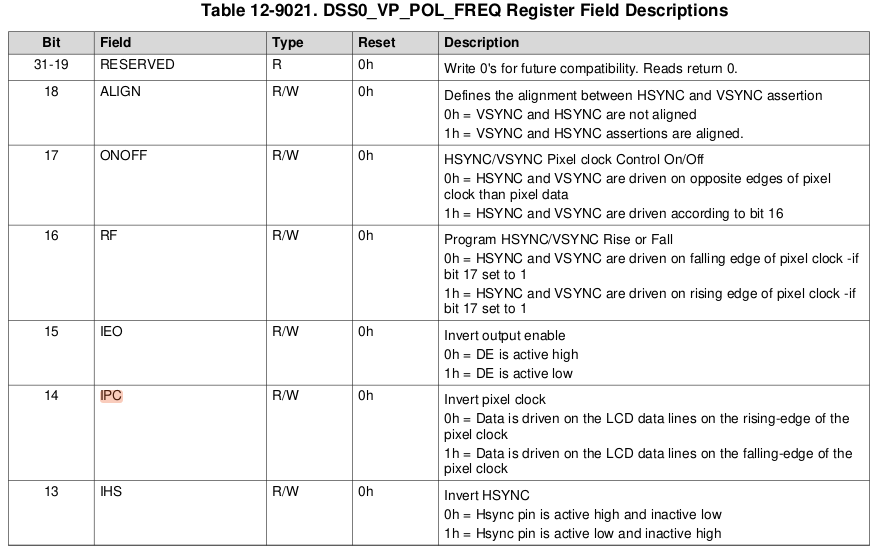
    • DCLK polarity: Negative (pixel data latched on falling edge)

    DRM configuration:

    .flags = DRM_MODE_FLAG_NHSYNC | DRM_MODE_FLAG_NVSYNC; .bus_flags = DRM_BUS_FLAG_DE_HIGH | DRM_BUS_FLAG_PIXDATA_DRIVE_NEGEDGE | DRM_BUS_FLAG_SYNC_DRIVE_NEGEDGE;

    LCD panel information (WF35XSWACDNN0#):

    • Resolution: 320 x 240
    • RGB interface with DE, HSYNC, VSYNC, and DCLK
    • Supports both positive and negative DCLK polarity
    • HSYNC: Active Low
    • VSYNC: Active Low
    • DE: Active High

    Timing specification summary from datasheet:

    DCLK Negative Polarity mode:

    • Pixel data (DIN) is sampled on the falling edge of DCLK
    • HSYNC and VSYNC are active low
    • HSYNC/VSYNC timing is referenced to the DCLK falling edge
    • Setup and hold times (Tdsu, Tdhd, Tdest, Tdehd, Thst, Thhd, Tvst, Tvhd) are defined relative to the falling edge
    • Continuous pixel data transfer from “1st data” to “Last data” during DE active high

    DCLK Positive Polarity mode:

    • Pixel data (DIN) is sampled on the rising edge of DCLK
    • HSYNC and VSYNC remain active low
    • DE remains active high
    • Timing parameters are defined relative to the rising edge of DCLK

    Question:

    Given this configuration and the LCD timing requirements, I would like to ask:

    1. Does AM62x DSS DPI output fully support pixel data and sync signal alignment on the DCLK falling edge?
    2. Is there any known limitation or internal behavior where the DPI output effectively assumes rising-edge sampling, even if negative edge polarity is configured via DRM bus flags?
    3. Are there any additional DPI or DSS configuration requirements (for DE mode panels) that could result in a black screen even when DRM/KMS and modetest report correct configuration?

    Any advice on whether there might be a configuration issue or an IP limitation would be greatly appreciated.

    Thank you for your support.

  •  Hi Fumiyuki-San,

    I have updated the panel timing to use a 7.0 MHz pixel clock and will first verify output using DE-only mode (HSYNC/VSYNC treated as dummy). The updated parameters are

    Before I answer your questions, can your panel support that high fps? Since your original requirement was for 60fps and that was too low clock for the SoC and hence you tried with 7MHz, but most DPI panels have a strict restriction on the fps they support and this could be the reason your screen is black.
    If possible, can you share your panel datasheet if it really does support 70-75fps?

  • Since you also have the DPI lanes exposed on your board, you can always probe PCLK,HSYNC,VSYNC and DE lines to check if these signals are coming out correctly as per your panel specifications or need polarity configurations.

  • Hi Divyansh-San,

    When I try to upload the datasheet, the following message is displayed and the upload fails:
    “We apologize, but an unexpected issue prevented the page you requested from being available. We've logged the issue so the site administrator can resolve the problem.”

    Therefore, I will contact support and ask them to help with sending the datasheet.

    Best Regard

    Fumiyuki 

  • Hi Divyansh-San,

     I have identified the URL for the datasheet, which is provided below, and have attached it to this email as well. Please kindly review it.

    https://datasheet4u.com/pdf-down/W/F/3/WF35XSWACDNN0-Winstar.pdf

    Best Regards,

    Fumiyuki

  • Hi Fumiyuki-San,
    Thanks for sharing the datasheet. As per your datasheet, it can support upto 8MHz, but the timing parameters would change. It would probably be a good idea to use 8MHz along with the parameters it specifies:

    DRM_BUS_FLAG_DE_HIGH

    This flag is correct per your datasheet.

    .flags = DRM_MODE_FLAG_NHSYNC | DRM_MODE_FLAG_NVSYNC; .bus_flags = DRM_BUS_FLAG_DE_HIGH | DRM_BUS_FLAG_PIXDATA_DRIVE_NEGEDGE | DRM_BUS_FLAG_SYNC_DRIVE_NEGEDGE;

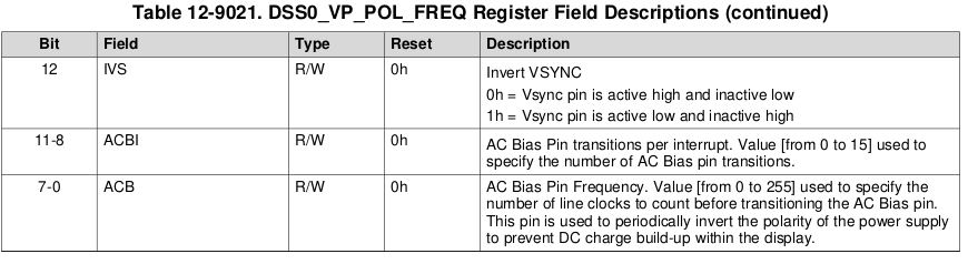
    From the timing diagrams, HSYNC, VSYNC maybe also be active high. Seems there is a way you can set the polarity in the panel on this (VDPOL,HDPOL).
    I would recommend trying multiple permutations to these flags incase not sure: like: {N(H/V)SYNC with NEGEDGE} or {N(H/V)SYNC with POSEDGE} or {P(H/V)SYNC with NEGEDGE} or {P(H/V)SYNC with POSEDGE}.

    The best way to check this out would be to probe the physical DE, HSYNC, VSYNC lines to validate if the output is what the panel is expecting.

    The following register (0x3020b04c) may also be helpful:

    Does AM62x DSS DPI output fully support pixel data and sync signal alignment on the DCLK falling edge?

    Yes

    Is there any known limitation or internal behavior where the DPI output effectively assumes rising-edge sampling, even if negative edge polarity is configured via DRM bus flags?

    No

  • Hi Divyansh-San,

    Thank you very much for your advice. I will try various configurations and would like to share the results once I get positive outcomes. I will also review and verify the points you highlighted.

    Best Regards,

    Fumiyuki

  • Hi Fumiyuki-San,
    I noticed these patches involved in incorporated in the latest 11.02 SDK, but since you are working on 11.00, these would need to applied separately, let me know if these help:
    https://e2e.ti.com/cfs-file/__key/communityserver-discussions-components-files/791/0001_2D00_FROMLIST_2D00_drm_2D00_tidss_2D00_Fix_2D00_sampling_2D00_edge_2D00_configuration.patch
    https://e2e.ti.com/cfs-file/__key/communityserver-discussions-components-files/791/0002_2D00_PENDING_2D00_arm64_2D00_dts_2D00_ti_2D00_k3_2D00_am62p_2D00_j722s_2D00_common_2D00_main_2D00_Add_2D00_.patch

  • Hi Divyansh-San,

    With the original configuration you shared, the panel size differs from our target panel, but the image is fully displayed using cropping.

    After modifying the panel size, reducing the clock to 8 MHz, and adjusting the resolution and back porch parameters, the display becomes black and the issue remains unresolved.

    We believe this is a timing-related issue on our side, and therefore we will proceed to close this ticket.

    Thank you very much for your assistance.