AM2732-Q1: AM2732 EVM debugger reset from CCS

Part Number: AM2732-Q1
Other Parts Discussed in Thread: AM2732

Hello,

Continuing from this thread https://e2e.ti.com/support/microcontrollers/arm-based-microcontrollers-group/arm-based-microcontrollers/f/arm-based-microcontrollers-forum/1592306/tmds273evm-tmds273evm-cs_dap_0-error-the-second-time-i-debug-the-tmds273evm-2
 

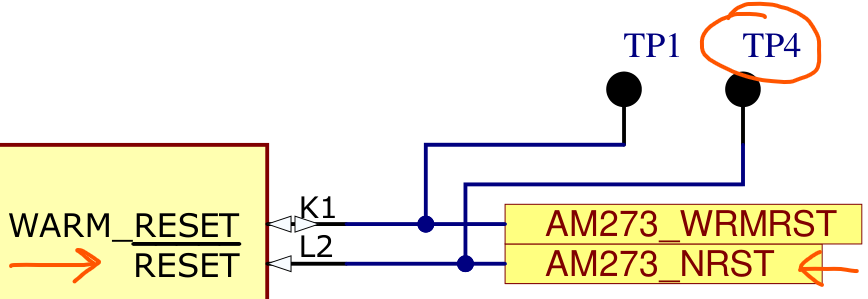
I would like connect the J19 pin 6 MIPI_NRST to the AM273_NRST (TP4 on the AM273x EVM) in order to issue the appropriate reset every time i debug my applications from the CCS 20.4.0 using a system project with R5Fs and C66, using an XDS560v2. The target is to test this connection, in order to proceed to a custom board design with this SoC.

  1. Are the following pins of J19 connector/XDS debugger (pin 6 MIPI_NRST and/or pin 9 MIPI_JTAG_NRST) used from the CCS every time a debug session is restarted?

    image.png
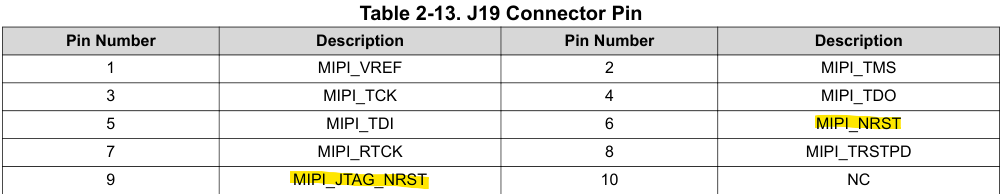
    When i initiate a debug session and when i reload a binary, nothing is changing to the pins 6 & 9 (measuring with an oscilloscope they are constantly high). What actions should be made in CCS in order for the MIPI_NRST signal to work properly? 

    image.png
  2. Is the connection of the J19 pin 6 MIPI_NRST to the AM273_NRST the appropriate way to reset the SoC from the debugger?
    image.png


Thanks in advance,
Konstantinos

  • Hello again, 
    Any news especially on question 1? How to trigger a reset from the debugger via CCS?

  • Hi Konstantinos, 

    I think what you are looking for is the System Reset functionality within CCS. This works with the XDS TI debuggers.  

    See CCS docs here: https://software-dl.ti.com/ccs/esd/documents/xdsdebugprobes/emu_resets.html

    See TI JTAG/TRACE debugger connector descriptions here: https://software-dl.ti.com/ccs/esd/documents/xdsdebugprobes/emu_jtag_connectors.html

    See "Table 12. MIPI 60-Pin Header Signal Naming Convention". 

    For the MIPI-60 XDS debuggers, I pin 6 "MIPI_NRST" is the system reset pin and should be what CCS XDS debugger drivers toggle when the system reset function is called.

    The location of the GUI controls for this system reset may change depending on the CCS version, but I think it should be under the Run Menu >  Reset > System Reset. Should also popup when right clicking on the currently loaded target debug configuration. 

    MIPI-60 pin 9 "JTAG_NRST" is the standard JTAG reset signal used to reset the attached device JTAG TAP. JTAG_NRST can be toggled by the attached debugger to reset the attached JTAG TAP. Depending on the debugger and its specific configuration, this might not toggle at all, or you might see just a single reset during power-on of the debugger. 

    Let me know if you have any trouble finding that specific system reset functionality or seeing activity on the appropriate MIPI_NRST pin. 

    Thank you,

    -Randy

  • Thank you for the detailed and documented response Randy,

    Setup:
    I have the AM2732 EVM connected with an XDS560V2 debugger to the J19 MIPI connector.
    Using an oscilloscope, i am monitoring the pin 6 "MIPI_NRST" (using a MIPI breakout adapter to easily capture the MIPI connector pins).


    Pin 6 monitoring:

    For the MIPI-60 XDS debuggers, I pin 6 "MIPI_NRST" is the system reset pin and should be what CCS XDS debugger drivers toggle when the system reset function is called.

    The pin 6 "MIPI_NRST" is constantly high (as it should because it is connected with a pullup resistor). However, the procedure "Run Menu >  Reset > System Reset" does not change the state of the pin 6.

    Target:

    Is the connection of the J19 pin 6 MIPI_NRST to the AM273_NRST the appropriate way to reset the SoC from the debugger?

    So i cannot perform this connection to the TP4 of the AM2732 EVM because CCS does not trigger the pin 6. Is there any other way to reset the board with the debugger as it should?

    My goal is to implement this functionality, because by design this EVM needs to be PORed with a switch every time a debug session is initiated, which is very difficult to work with (other EVMs are resetted by just issuing another debug session). 


    Am i missing something? CCS seems to ignore the toggle of the pin 6 of the debugger with a CCS System Reset. Is it specific for the AM2732 EVM?


  • Hi, 

    If the system reset menu item isn't toggling pin 6, then there might be some issue with either the emulator HW/firmware, or CCS implementation of this feature. Which CCS version are you using? I'd like to bring this up with the CCS support team. 

    -Randy

  • I am using:
    CCS: 20.4.0.13__1.10.0
    Blackhawk USB560v2 swRev: 5.0.573.0

    Can you please verify if CCS toggles the pin as it should?

  • Can you please verify if CCS toggles the pin as it should?

    I don't have the hardware expertise to answer this specifically. But what i can say is that when I connect my Blackhawk XDS560v2 debug probe to the MIPI connector J19 on my AM273 EVM and then issue a System Reset from CCS (Run > Reset > System Reset), the debugger receives the System Reset command and successfully performs it on the target. What exactly this command does on the target depends on the device so I will defer to the device experts on this. But I can see that the system reset was issued and executed on the target.

  • How do you verify that the reset is successfully performed to the target?
    The command does execute in the UI but i cannot check its effect. Neither of the J19 pins 6 & 9 are connected to the SoC, so what does the System Reset from CCS?


  • How do you verify that the reset is successfully performed to the target?

    By enabling additional diagnostic logs (Debug Server Logs), I analyzed the log with engineering and we can see that the system reset command was issues by the debugger and the driver performed some actions on the target. 

    As per engineering:

    The driver read 0x6 and wrote 0x7 (i.e. we set bit 0) to the register at offset 0xF0 on AP 7 (that's what the 0x207F0 means).
    According to the device xml file, this is the SPREC register on the PWR-AP. According to the PWR-AP spec for the mspm0, bit 0 is SYS RST bit. As far as I know, the system reset bit is the same across all PWR-AP implementations.

    So I would say that it looks like we are doing the right thing given the device xml files.

    So from the CCS/driver side, it looks like it was successful. For whether the correct target actions are actually being performed is more question for the device experts.

    Thanks

    ki

  • Hi Ki, 

    Konstantinos is attaching the XDS560V2 to one of our https://www.ti.com/tool/TMDS273EVM

    This target EVM just routes the J19.6 MIPI_NRST (System reset) signal to a 4.7k pull-up on the board and nowhere else. We didn't implement anything explicitly, but Konstantinos wants to mod the board to make use of this signal. When probing that signal though he is seeing no toggling at all. 

    The driver read 0x6 and wrote 0x7 (i.e. we set bit 0) to the register at offset 0xF0 on AP 7 (that's what the 0x207F0 means).
    According to the device xml file, this is the SPREC register on the PWR-AP. According to the PWR-AP spec for the mspm0, bit 0 is SYS RST bit. As far as I know, the system reset bit is the same across all PWR-AP implementations.

    What were you referencing here? What that something specific to the XDS560v2 driver and firmware? I no longer have this emulator available to test with myself. In this case the target board behavior is not going to effect the pin behavior. Konstantios was just probing the MIPI-60 pins to see the expected toggle and is not. 

    There is nothing on the target EVM to stop this signal, so I am suspecting something might be different on the drivers/CCS SW/XDS560V2 FW chain and has not been verified in a long time. Can someone in SDTO verify that this register write actually toggles the XDS560V2 pin as expected?

    Thanks,

    -Randy

  • Hi Randy,

    It's been a month. Do you have any news or updates yet regarding this issue?

    Best regards,

    Konstantinos