This thread has been locked.

If you have a related question, please click the "Ask a related question" button in the top right corner. The newly created question will be automatically linked to this question.

Boot problems with OMAP L138B

Other Parts Discussed in Thread: OMAP-L132

Hello everybody,

 I have serious problems with the series production of our CPU PCB.

We are using the OMAP L138B and the standard boot configuration is 02h.

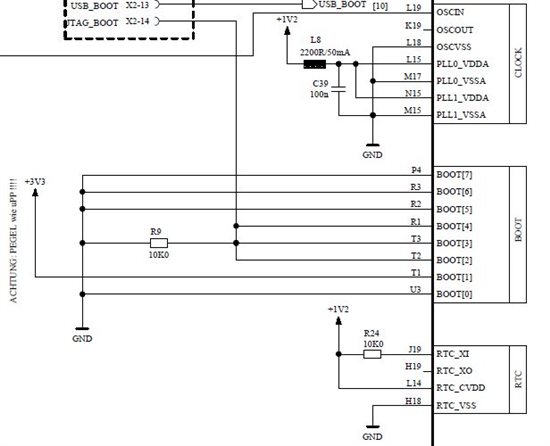
As we als want to boot with the JTAG interface, we connected the pins BOOT[2], BOOT[3], BOOT[4] with an external pulldown resistor to GND,

as shown in the following schematic.

80% of all PCB works fine and there is no start-up / boot problem.

Unfortunately, the remaining 20% has some problems.

The OMAP is stated in a dead-lock loop because it waits for an external emulation debug boot.

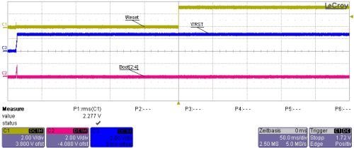
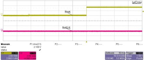
I have recorded the states of the boot pins [2]-[4] and the scope diagramm shows following:


There´s a small glitch 240 ms before the rising edge of the reset. At the time of the rising edge,

the state of the boot pins is low ! Thus, the boot value should be 02h and not 1Eh !


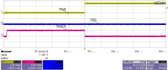
I tried to use a stronger pulldown and change the resistor value to 1k. The result is:

The glitch is smaller than before, but the state at the moment of rising edge is low.

But, compared to the diagramm before, the OMAP starts und is booting !

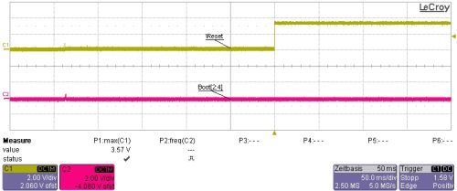
I also compared this states with a PCB which has no problems:

 Here, there is no glitch before the rising edge, but the pulldown resistor has still the value of 10k !


Now, I have problems to understand this !  We have no problem to change the resistor value from

10k to 1k... but, is this the solution ? Is there anything else, we don´t know yet ?

According to SPRAD41D.PDF "Using the OMAP-L132/L138 Bootloader", Appendix A the rising edge

of the reset is the master !

"The boot pins are latched by the bootloader when the device exits reset (i.e., on the rising edge of reset)."

At that moment the state of the boot pins are always low and the value of 1Eh should not be latched !


 Additional note:

We use an external watchdog which produces a reset after 1.8 s if it is not retriggered by the OMAP,

according to advisory 2.0.20, Errata sheet sprz301e.pdf.

Even after these resets, the OMAP fails to boot. It seems that the correct boot configuration is not newly

latched if the boot configuration is wrong at the first time !


Please, I really need help, cause at the moment our production is stopped !

Thx in advance !

Andreas Amler


  • Hi Andreas

    Do you have a TI local field/sales office contact that could be assisting you on this issue?

    Regards
    Mukul  

  • Hi Mukul,

    I have already contacted my local office with this issue, but there was no response yet.

    Thus, I had the hope, that I could some get some help by the forum.

    Regards,

    Andreas 

  • What is the state of TRST during the boot? I cant see it on the schematic, but is it pulled low?

    On the failed boot, have you connected in CCS using the debug GEL to verify that the wrong boot mode was in fact latched?

    Jeff

  • Hi Jeff,

    instead of using CCS for debugging, we use a Lauterbach debugger. My SW colleague verified that the boot mode is wrong because the value in the BOOTCFG register is 0x1Eh.

    The \TRST has an external pullup (blue line). So, every reset is like a warm reset.

    It seems, that this wiring is an error !

    It seems that with the rising edge of the \TRST the wrong states of the boot pins are latched caused by the glitch.

    As all following resets are warm resets, the wrong boot mode is not changed. 

    After your post, I´ve made to two tests:

    a) connecting the \TRST hard-wired to GND

    first, the wrong boot mode was latched, after the reset of the watchdog the OMAP booted correctly

    b) removing the pullup resistor and the wire to GND and leave the pin floating

    first, the wrong boot mode was latched, after the reset of the watchdog the OMAP booted correctly

    In both tests at first the state of the boot pins was high, so the wrong boot mode was latched.

    After the rising edge of the reset, the state of the boot pins went low and the OMAP booted correctly.

    It seems that a warm reset doesn´t re-latch the boot pins by the rising edge of the reset.

    I think we have different options now:

    i) connecting the \TRST pullup to GND

    ii) using a pulldown resistor instead of the pullup resistor (\TRST)

    iii) leaving the \TRST pin floating

    iv) using a strong pulldown resistor (<1k)  instead of  the 10k at the boot pins

    Option ii) is a long-term solution because it requires a redesing of the PCB

    Option i) is possible but it requires an additional wire soldering by hand -> higher manufacturing costs   -> not the prefered solution

    Option iii) is possible but it is no good solution !

    Option iv) is maybe the best short-term solution for our problem.

    If you or anybody else has further more solution, please feel free to post it  ;-)

    I´m grateful for any other solution !

    Andreas

  • Andreas, yes TRST must be pulled down to boot properly every time. See the following document for details:

    http://processors.wiki.ti.com/index.php/OMAP-L138_Bootloader

    So are you saying that even with TRST tied to ground, the board still failed to latch the correct boot mode when powering up? Can you provide a scope shot of this scenario, including RST, TRST, and one of the low boot pins?

    Can you connect with your emulator after the failed boot and read the memory location 0xFFFF0700?

    Thanks,

    Jeff

  • Andreas

    Option iv looks good. I am also trying to get hold of the local team supporting you on this, that way if you have any additional issues/concerns or if we missed any failure details here, we will be able to close with you further on a one on one call.

    Regards

    Mukul 

  • Jeff,

    unfortunately, my SW colleague was in a meeting the whole day.

    So, here are the results:

    This is the scope shot of the first (failed) boot attemp. The TRST is tied to GND. The external pulldown is too weak holding the boot pins low and the voltage rises up to ~2 V.

    After the rising edge of the RST, the internal pullups are disabled, but the wrong boot configuration is latched.

    After the reset of the external watchdog the correct boot configuration is latched and the OMAP starts to boot.

    But this works only if the TRST is low.

    My colleague read the memory location 0xFFFF0700 and the value is 0x00000000.

    But he also read the following memory because he is not available today.

    ___address____   ________0   ________4  ________8  ________C

       SD:FFFF0700        00000000     00000000     00000000    001E0000    ................

       SD:FFFF0710        00000001     00000000     00000000    00000000    ................

       SD:FFFF0720        00000000     00000000     00000000    00000000    ................

       SD:FFFF0730        00000000     00000000     00000000    00000000    ................

       SD:FFFF0740        FFFD42C8   FFFFFFFF      00000000    00000000    .B..............

       SD:FFFF0750        00000000     00000000     00000000    00000000    ................

       SD:FFFF0760        00000000     00000000     00000000    00000000   ................

       SD:FFFF0770        00000000     FFFD4290     00000000    00000000   .....B..........

       SD:FFFF0780        00000000     00000000      00000000    00000000   ................

       SD:FFFF0790        00000000     00000000      A49F972D   31FBC94D   ........-...M..1

       SD:FFFF07A0        42608470     2E62E4C1    734265A0    E39285BC    p.`B..b..eBs....

       SD:FFFF07B0       30962B9A      0FA03862     A2AD5406   AD6D8986   .+.0b8...T....m.

       SD:FFFF07C0       5412C856     503BC4DE    5E43F488   D332CC85    V..T..;P..C^..2.

       SD:FFFF07D0       2A4D0668     BF755CC2    BFDF37EE   370734AF    h.M*.\u..7...4.7

       SD:FFFF07E0       60B6E706     BD344684     62030310    1202C4B7     ...`.F4....b....

       SD:FFFF07F0       F4EDC650    01306C6D     CA03A6E8    91492B15   P...ml0......+I.

       SD:FFFF0800       73CAB291     2123A886      36C1C299    71AFEC9B   ...s..#!...6...q

       SD:FFFF0810       3E630702      60377620      B2AB6E5A    72DBF9D2   ..c> v7`Zn.....r

       SD:FFFF0820       3EA7A1D0     70072180      37814499     320602D0    ...>.!.p.D.7...2

       SD:FFFF0830       08099590      1084624B      120F1870     22D57BB6   ....Kb..p....{."

       SD:FFFF0840       B967C09C     33E9E416     BC408CC8    FB5A8476   ..g....3..@.v.Z.

       SD:FFFF0850       D28F0291      06FA7A8F     31480745       2E9AFDCF   .....z..E.H1....

       SD:FFFF0860      03C70018       B15548C8     6868D3B5     B782F581    .....HU...hh....

       SD:FFFF0870      1F08A51B       ACAB507D     027BC315    3FA5FBF2     ....}P....{....?

       SD:FFFF0880      93F46021       7B20B7C2      A806D090    2BB7B4EE    !`.... {.......+

       SD:FFFF0890     9B2D4716       2465B712       D4CB3221   38B67990    .G-...e$!2...y.8

    Thanks for your support !

    Andreas