This thread has been locked.

If you have a related question, please click the "Ask a related question" button in the top right corner. The newly created question will be automatically linked to this question.

AM62L: Custom AM62L32 board MIPI DSI display abnormal

Part Number: AM62L

1.After switching the device tree for the MIPI interface on the TL62Lx-MiniEVM, pressing the reset button (POR or WARM) causes the system to reboot, but the MIPI display (AML070WXII4006) shows no image except the backlight

 2.After switching the device tree for the MIPI interface on the TL62Lx-MiniEVM, the system reboots normally (either via power cycle restart or by entering "reboot" via the serial port), and the MIPI display (AML070WXII4006) displays correctly after the driver is loaded

3.After removing the reset IO resistor R289 of the MIPI display, switching the device tree for the MIPI interface on the TL62Lx-MiniEVM, and then rebooting the system (via pressing reset buttons POR/WARM, power cycle restart, or entering "reboot" via the serial port), the MIPI display (AML070WXII4006) displays correctly after the driver is loaded

4.After changing the MIPI display reset IO resistor R289 to 1Mohm and switching the device tree for the MIPI interface on the TL62Lx-MiniEVM, the MIPI display (AML070WXII4006) functions correctly after driver loading following a system reboot (via POR/WARM reset buttons, power cycle, or the "reboot" command over the serial port). 

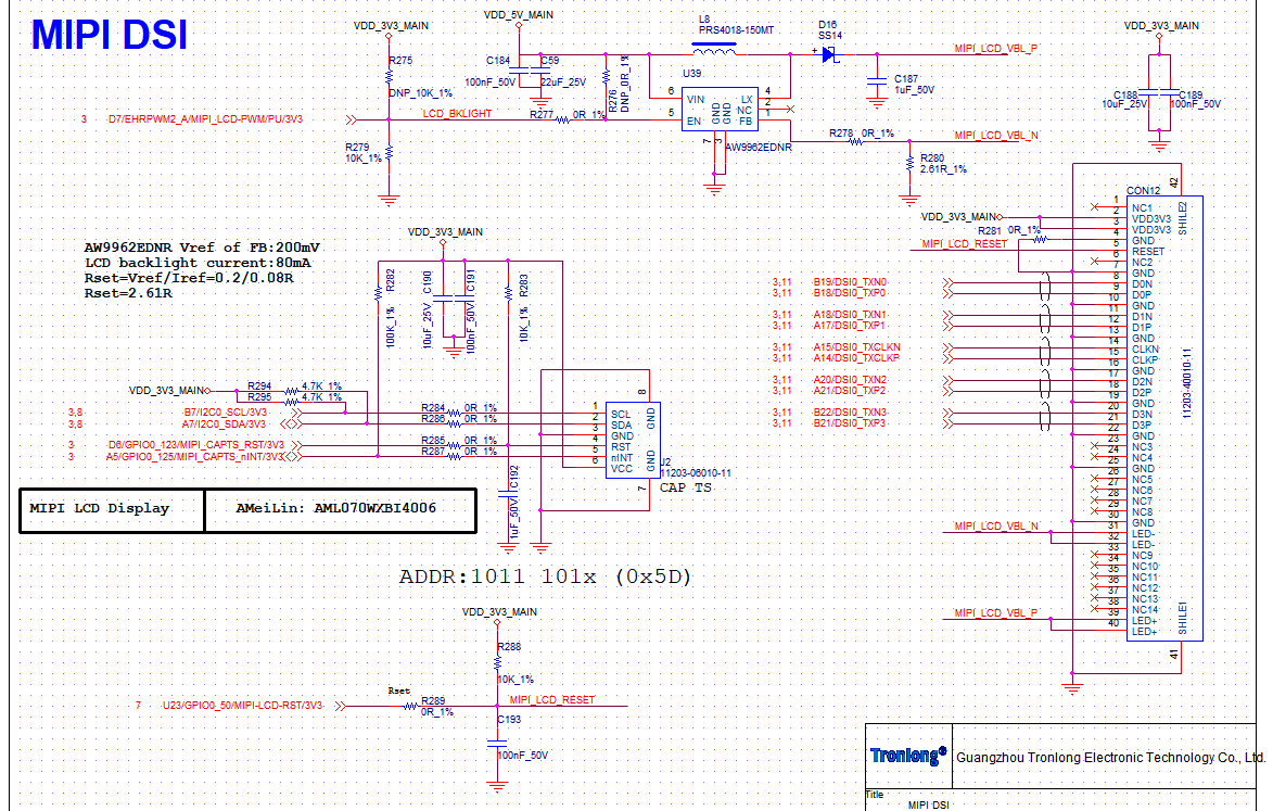
The schematic diagram is as follows:

MIPI-2.png

MIPI-1.png

  • Hello Junji Wu,

    Please check with the below changes

    C193 - DNI, populate a 10K resistor 

    R288 DNI

    Connecting a large cap at the output of SOC IO is not allowed or recommended.

    Regards,

    Sreenivasa

  • Hi Sreenivasan,

    C193 - DNI, populate a 10K resistor 

    Do you mean replace C193 with a 10K resistor? that will be a voltage divider.

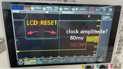
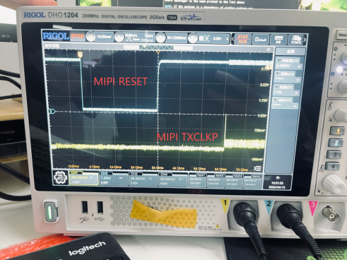
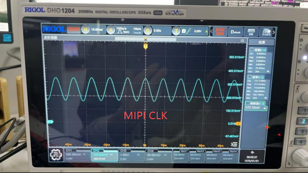
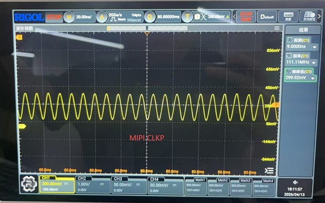
    Below is the waveform of LCD_RST and clock.

    The single clock vpp is ~80mv, it should between 140-270mv from google, is it a problem?

    Actually the LCD_RESET signal is output to LCD, if the signal integrity meet requirement should be OK.

    R288 DNI

    Is it a typo? It was mentioned DNI R288 can make board work.

  • Hello Tony,

    R288 DNI

    Is it a typo? It was mentioned DNI R288 can make board work.

    R288 is the pullup for MIPI_RESET

    C193 replaced with a 0K is the pulldown for reset.

    R280 is 0R 

    Depending on the reset polarity mount a pullup or pulldown to hold the LCD in reset until the SOC IO releases the reset.

    Connecting a large cap at the SOC IO output is not recommended or allowed.

    Regards,

    Sreenivasa

  • #1. Sorry for my mistake.

    #2. In order to describe the issue clear, make a table:

    RESET mode LCD status MIPI_RST pulse width
    Power Up Work 36.5ms
    Reboot command in Linux Work 36.8ms
    PORz Pin only have backlight 37.8ms Reboot in Linux, display  Normal
    WARM reset Pin only have backlight 40.4ms Reboot in Linux display normal

    Depending on the reset polarity mount a pullup or pulldown to hold the LCD in reset until the SOC IO releases the reset.

    Understand your purpose, can take a try to verify if it is the problem.

    Connecting a large cap at the SOC IO output is not recommended or allowed.

    It is a widely adopted method to avoid unexpected reset by noise or interference, I think your conclusion comes from slew rate requirement of K3 device, it may impact the IO life time, should not impact the functionality of this issue.

    From Linux SDK dts file, I see k3-am62l3-evm-dsi-rpi-7inch-panel.dtso, so AM62 EVM should be verified with raspberrypi lcd: https://www.raspberrypi.com/documentation/accessories/display.html, it has not a RESET pin. 

  • Hello Tony,

    Thank you.

    PORz Pin only have backlight 37.8ms Reboot in Linux, display  Normal
    WARM reset Pin only have backlight 40.4ms Reboot in Linux display normal

    Please elaborate the test sequence.

    Regards,

    Sreenivasa

  • Please elaborate the test sequence.

    It doesn't matter with test sequence. Just behave difference with different reset source/menthod.

    For example, the system is working, Push PORz reset pin or Warm reset pin, the MIPI LCD doesn't display after Linux launch up.  then key in reboot in Linux console, MIPI display works after Linux up again.

  • Hello Tony,

    Thank you.

    I am checking with the software expert if he has any comments.

    Can you elaborate how the PORz and RESETz is being connected to SOC?

    Regards,

    Sreenivasa

  • Hi Sreenivasan,

    The following image shows the schematic for the PORz and RESETz signals.

  • I am checking with the software expert if he has any comments.

    As there is a mipi display dtso file in SDK for AM62L, so I think the MIPI display is verified on AM62L EVM, who has the test environment with MIPI panel can  also try POR or WARM RESET without power cycle to see if has same issue as that on customer's board.

  • Hi Tony,
    This has been tested multiple times on the TI EVM (and I have rechecked to make sure) that the k3-am62l3-sk-dsi-rpi-7inch.dtbo DSI overlay works with all: PORz, RESETz and hard power replug.

  • Hello Juni Wu,

    The following image shows the schematic for the PORz and RESETz signals.

    The slow ram RC connected as inputs to PORz and RESETz is a concern.

    Can you please measure the ramp.

    We expect the ramp to be <100ns since the reset input have hysteresis internally implemented.

    Regards,

    Sreenivasa

  • Hi Divyansh,

    As the raspberry pi 7inch display has not reset pin, it can't mimic the same use case.

    How do you think if MIPI display need a RESET pin?

  • Hi Tony,
    We do not have any usecase (even internally) utilising a reset pin on DSI panel. Not sure what the reset signal on the panel is being used for, but highly depends on the panel itself.

    In the customer case, you mentioned hard power replug works, but PORz doesn't. Both of these eventually reset the PMIC so should result in the same observations. Also, the RESET signal in the customer setup is created from a GPIO line, which would get signals on correct panel driver probe. 
    If there is a diff in both these cases, please share any error logs you are getting in the non-working case.

  • Hi Divyansh,

    #1. Search from Google get AI answer as below, there should be a RESET process before initialization. AM62L EVM selected a RaspberryPi panel which has not RESET pin is not a typical use case.

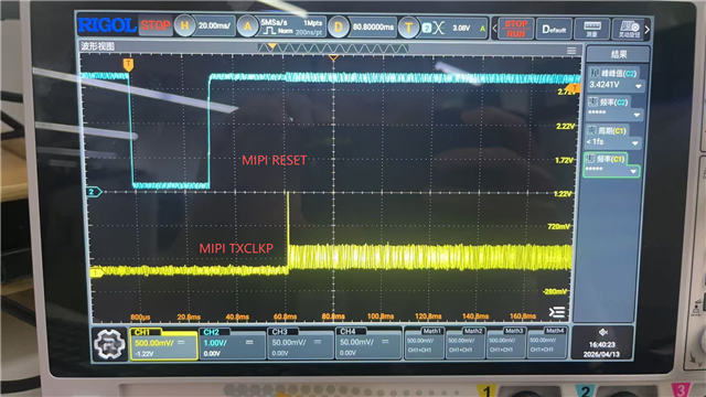
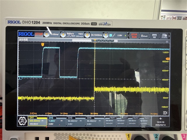
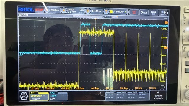
    #2. On custom board, push on PORz or WARm reset pin doesn't reset PMIC, only reset AM62L, during MIPI driver initialization, it will toggle GPIO to reset MIPI panel.  The blue signal in below snapshot is RESET/GPIO.

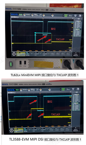
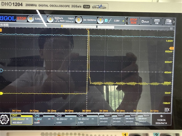
    #3. There should be a 1.2V DCS stage followed by RESET rising edge, before data stage, which configures MIPI panel. but did not see that on wave. only see one pulse reach 1.2V (the upper snapshot of upper). Is the DCS stage must, something wrong result in DCS stage did not get executed?

    #4. After reboot command in Linux, the MIPI display output correctly. what is the difference between reboot command and pushing PORz/Warm reset pin? is reboot writing a register bit to trigger reset?

    #5,. Even previous status is MIPI panel doesn't display, after a reboot command in Linux, it will display correctly.

    #6. Disconnect the Reset signal between AM62L and MIPI panel, MIPI panel display correctly always no matter how to reset AM62L.

    Please suggest what to investigate. 

  • Hi Tony,
    Few questions:

    #6. Disconnect the Reset signal between AM62L and MIPI panel, MIPI panel display correctly always no matter how to reset AM62L.

    If the above is the case, why not keep it disconnected?

    On custom board, push on PORz or WARm reset pin doesn't reset PMIC, only reset AM62L, during MIPI driver initialization, it will toggle GPIO to reset MIPI panel.  The blue signal in below snapshot is RESET/GPIO.

    So the issue you're seeing is that there is a difference between the GPIO toggling between different kind of resets? In the issue case, the GPIO does not toggle entirely, or is it delayed?

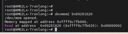
    Can you share the value of the following register in each kind of reboot/reset you have tried:

  • If the above is the case, why not keep it disconnected?

    Need to know why, as all test are limited, must figure out root cause when find one.

    So the issue you're seeing is that there is a difference between the GPIO toggling between different kind of resets? In the issue case, the GPIO does not toggle entirely, or is it delayed?

    No, the bottom picture is captured from competitors RK3588 board. The difference is yellow channel. on RK3588, the 1.2V signal is wider than that on AM62L, on AM62L, the 1.2V stage is just a pulse. 

    The reset signal is in BLUE channel. the pulse width is summarized in upper, copy here again.

    RESET mode LCD status MIPI_RST pulse width
    Power Up Work 36.5ms
    Reboot command in Linux Work 36.8ms
    PORz Pin only have backlight 37.8ms Reboot in Linux, display  Normal
    WARM reset Pin only have backlight 40.4ms Reboot in Linux display normal

    Reset source register value after power up in sequence in below, there is not power cycle between each operation.

    Power up: 0x0

    Reboot: 0x2

    Push Warm reset pin: 0x3

    Push PORz pin: 0

  • attach the log of each for your analysis, 

    PORz:

    /cfs-file/__key/communityserver-discussions-components-files/791/62Lx-MIPI_2D00_abnormal_2D00_LOG_2D00_PORz.txt

    reboot:

    /cfs-file/__key/communityserver-discussions-components-files/791/62Lx-MIPI_2D00_good_2D00_LOG_2D00_reboot.txt

    dsi is initialized on either reset/boot:

    [ 19.663359] panel-aml070wxii4006 30500000.dsi.0: dsi video mode[0x813]
    [ 19.668027] [drm] Initialized tidss 1.0.0 for 30200000.dss on minor 0

  • Hi Tony,

    Need to know why, as all test are limited, must figure out root cause when find one.

    Keeping the reset pin grounded or active high (whichever works) may be the correct panel usage.

    Not sure why you are comparing waveforms between Rockchip and AM62L. Please provide the waveform difference on AM62L comparing the working and non-working case. I assume the reset signal you are probing is the GPIO reset pin for DSI and not the RESETz.

    From what you are mentioning, lets consider the following 2 cases:
    1) Power-up / PORzrst_src value is 0x0
    What is the difference the the DSI GPIO RESET line in both cases?
    2) Reboot / Warm-reset with button value is 0x2/0x3
    What is the difference the the DSI GPIO RESET line in both cases?

  • Not sure why you are comparing waveforms between Rockchip and AM62L. Please provide the waveform difference on AM62L comparing the working and non-working case. I assume the reset signal you are probing is the GPIO reset pin for DSI and not the RESETz.

    The same panel works with competitor's board. migrated the panel driver from RK3588 to AM62L, it works except the issue described. 

    Yes, it is GPIO controlled MIPI_RST.

    Keeping the reset pin grounded or active high (whichever works) may be the correct panel usage.

    But the same panel works on RK3588 with GPIO controlled MIPI_RST in same way.

    There is not much difference of MIPI_RESET/GPIO, add one column to the table, the trival difference is the MIPI_RST(Blue) width and delay between TXCLKP and MIPI_RST rising edge.

    RESET mode LCD status MIPI_RST pulse width MIPI_TXCLKP to MIPI_RST rising edge
    Power Up Work 36.5ms 36.3ms
    Reboot command in Linux Work 36.8ms 36.4ms
    PORz Pin only have backlight 37.8ms 35.4ms Reboot in Linux, display  Normal
    WARM reset Pin only have backlight 40.4ms 36.2ms Reboot in Linux display normal

  • Hi Tony,

    migrated the panel driver from RK3588 to AM62L

    Can you please explain what you mean by migrated? Were there any changes made to the panel driver?

    1) Power-up / PORzrst_src value is 0x0
    What is the difference the the DSI GPIO RESET line in both cases?

    Keeping the working scenario with competitor board aside (but noted),
    Let may ask you this:

    You have a working and non-working scenario in power up vs PORz. Can you tell me what difference on the data / reset / gpio lines you see in both these cases?

  • Hi,Divyansh

    Our driver was ported from the RK3588 platform to the AM62L, and no significant modifications were made to the driver. Based on the currently measured waveforms, the driver loaded during power-up and PORz is the same. 

    The GPIO reset signal of the MIPI interface is basically consistent, and the MIPI clock (CLK) is also basically consistent. However, there are differences in the amplitude of the data waveforms.

  • Hi All, 

    Please expected delay in response due to Good Friday Holiday.

    Regards,

    Sreenivasa

  • Hi yi wang,
    Is it possible to share all waveform differences between GPIO RESET, DSI CLK, DSI data lanes between power-up and PORz?

  • Power up waveform 

  • Hi Victor,
    Can you please also share the same for PORz for us to be able to compare?

  •  PORz waveform

  • Hi Victor,
    It seems like your panel is not getting reset at all using the GPIO RESET signal, rather, it may be using the VDD power from your board supplied through the DSI cable to power itself.
    Hence, during power off/on, VDD via DSI cable goes off/on triggering a panel reset, but,
    PORz/RESETz still have the PMIC suppying the power, and the VDD through DSI cable doesn't toggle leading to no reset in you DSI panel.

    Would recommend you to check this with your panel vendor.

  • Hi,Divyansh

    The timing diagram in below includes the startup sequence of the Panel.

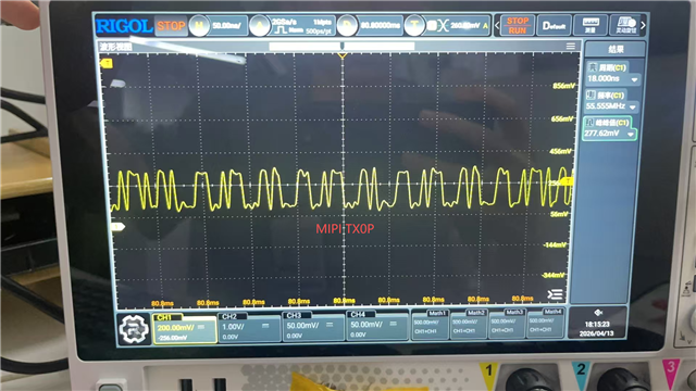
    According to the panel manufacturer's requirement, before the RESET signal goes high, the MIPI LP11 needs to go high first. Moreover, the reset operation is performed while the MIPI LP11 remains high, as shown in the red timing sequence in the figure below (the red timing sequence was provided by the manufacturer, and the waveform captured from another vendor's platform).

    But the LP11 duration is about 0.4ms on AM62L custom board as shown below.

    Support needs. How to control/adjust the LP11 timing.

  • In the video display framework I am using, can this LP11 timing be adjusted to meet the requirements?

  • Hi,
    Discussing this internally with the dev team, will get back by end of this week.

  • Hi,
    Can you please check you panel driver and see what this value is being set to: prev_enable_first? Try toggling it and see what happens.

  • Hi,Divyansh

    I reviewed the driver code for the panel and found that there is no configuration for pre_enable_prev_first. I added the configuration ctx->panel.prepare_prev_first = true; during initialization. After that, I observed that both rebooting and using the reset button to perform a reset allow the screen to output images normally. Below are the reset waveforms after this configuration.

  • This shows the reset timing and D0P data signal measured after adjusting the reset pin timing, which can meet the reset timing requirements specified in the screen's datasheet

  • Hi Wang,
    Glad your issue is resolved.
    Just out of curiosity, can you please share how you changed the short delta peak on DSI0TXP to a longer pulse?

  • Hi,Divyansh

    Initially, the short delta peak was a measurement error — it was actually measured on the clock signal. The long LP11 pulse needs to be measured on DSI0TXP. That was our mistake in the description.However, modifying prepare_prev_first did solve the issue where the display failed to work properly due to the lack of a proper reset

    Without configuration ctx->panel.prepare_prev_first = true; the timing as below, which doesn't work, the LP11 is very short and output after RESET release.

  • Hi Wang,

    Thank you for the inputs.

    Regards,

    Sreenivasa