This thread has been locked.

If you have a related question, please click the "Ask a related question" button in the top right corner. The newly created question will be automatically linked to this question.

SK-AM62P-LP: EVM Not Powering On After Runtime

Part Number: SK-AM62P-LP
Other Parts Discussed in Thread: AM62P, LM5141, AM623

Hi Experts,

We are using the AM62P SK EVM for an DMS camera application. The board was functioning normally and running a camera pipeline demo. During runtime, the board suddenly powered off and is no longer booting.

Board revision: PROC164E2

Current observations:

  • USB-C(PWR) input voltage is present (12.09V via PD negotiation) (TP204)
  • Input voltage present at VMAIN( TP82) = 12.09V
  • Only one LED glowing. (USB PWR LED)
  • No output voltage observed on inductors (L1/L2/L4) in the LM5141 power stage
  • No voltage across bulk capacitors (near KEMET capacitors)
  • No heating observed on power components
  • Board shows no boot activity (no rails, no UART output)

Please help us with this.

Thanks and regards.
Eliza

  • Hello Eliza

    Thank you for the query.

    Please request customer to elaborate the failure sequence - any external input applied or abrupt power removal or handling the board in an uncontrolled ESD environment.

    I need some more input from the board, Is it possible to ask them to measure the below test point and share the values? 

    1. TP85 – VCC_5V.
    2. TP68 – VCC_3V3_MAIN
    3. TP46 – PMIC_LPM_EN0
    4. TP208 – CAN_IO_3V3

    Does customer have another board to compare the measurements?

    Regards,

    Sreenivasa

  • Hello Team,

    I am trying to reply to the thread but website is not allowing me to do so. It says you should use a company email address. My email address is company email address (@lumaxmail.com).
    Tries with clearing browsing data, with different browser, but no help.
    Could you please help me on this?

    And for now could you please post the below reply to the thread:
    Hi Sreenivasa,

    Please find the details of the failure sequence below:

    No external inputs beyond the intended setup were applied.
    External HW connected were, hdmi, ethernet cable, ftdi, camera, sdcard
    The camera module was connected via the CSI interface, and the DMS pipeline was running at the time of failure.
    There was no abrupt power removal, the board stopped functioning suddenly during normal operation.
    No known ESD events occurred.
    Value of the test points:

    TP85 – VCC_5V = 5.09V
    TP68 – VCC_3V3_MAIN=3.31V
    TP46 - PMIC_LPM_EN0=0.32V
    TP208- CAN_IO_3V3=3.31V
    We dont have any other board.

    Regards,
    Eliza 

  • Hi All,

    Thank you

    TP46 - PMIC_LPM_EN0=0.32V

    This being low may not allow the PMIC to start.

    Can you please measure TP42, TP43, TP54, TP55, TP56.

    Checking if you have the setup to make some changes (soldering, etc)

    PMIC_LPM_EN0: Function, Behavior, and Design Guidance

    PMIC_LPM_EN0 is a dual-function processor output pin that controls PMIC power states — acting as an active-high PMIC enable or active-low low-power mode trigger depending on the processor's current power state [1].


    Pin Characteristics

    Attribute
    Detail
    Function
    Low Power Mode control (active-low) / PMIC Enable (active-high)
    Signal Type
    Push-Pull output, 1.8V or 3.3V [2]
    Power Domain
    VDDSHV_WKUP (VDDSHV_CANUART pull-up required) [3]
    Default Controller
    WKUP R5 firmware [4]
    Alternate Function
    MCU_GPIO0_22 (MUXMODE=7, CTRLMMR_WKUP_PADCONFIG28) [5]
    Pin Ball
    B7 (AM623/ALW), D12 (AM62D/AMC) [3][6]

    Operational State Machine

    1. During Reset (HiZ) The pin is high-impedance during reset. An external pull-up to VDDSHV_CANUART holds the line high, enabling the PMIC immediately as the supply ramps up — no processor intervention required [1][3].

    2. After Reset Release On the rising edge of MCU_PORz, the pin is actively driven high and remains high throughout normal operation [1][3].

    3. Entering Deep-Sleep / Partial IO Mode The pin is driven low, signaling the PMIC to execute an orderly power-down. In Partial IO mode, this directly de-asserts the PMIC EN pin, shutting all rails off [7]. In IO+DDR mode, it drives the PMIC's nSLEEP2/GPIO3 input, turning off all rails except DDR and 1.8V analog supplies [7].

    4. Wakeup When the Partial IO logic detects an external wakeup event (e.g., CAN/UART activity), the pin is driven high again to re-enable the PMIC [1][3].

    5. RTC-Only Mode The RTC module can independently drive PMIC_LPM_EN0 low to enter RTC-only mode (cycling power to all non-RTC rails) or RTC+IO+DDR mode (cycling VDD_CORE and 1.8V analog rails) [8][9].

    Regards,

    Sreenivasa

  • Hi Sreenivasa,

    We have setup to solder.
    Please find the value of the test points below:
    TP42:0V
    TP43:0V
    TP54:0V
    TP55:0V
    TP56:0V

    Thank you.

    Regards,
    Eliza

  • Hello Eliza, 

    Thank you for the measurements.

    As mentioned above, the PMIC is not starting since the LPM_EN0 pin is low.

    One way to check is to isolate the LPM_EN0 pin from SOC going to PMIC.

    Let me check if the EVM team has some suggestions.

    Regards,

    Sreenivasa

  • Hello Eliza, 

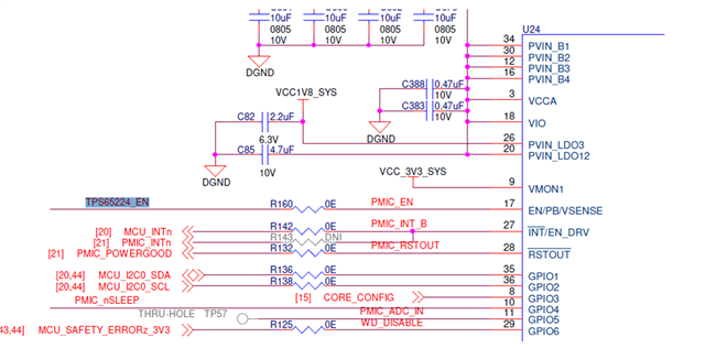
    Below is the suggested rework to bypass PMIC_LPM_EN0 connected to PMIC.

    Please remove R160 and solder a glue wire from PMIC_EN to R429 (VCC_3V3_MAIN_PG). 

    Please verify the PMIC outputs after making the above change.

    Regards,

    Sreenivasa

  • Hi Sreenivasa,

    Thank you for sharing the suggested rework.

    We will proceed with removing R160 and connecting PMIC_EN to R429 (VCC_3V3_MAIN_PG) shortly and will update you once the rework is completed and validated.

    In parallel, could you please help us understand what might have caused this issue? This will help us ensure we avoid similar problems in future.

    Thanks and regards,
    Eliza

  • Hello Eliza

    Thank you.

    The most likely reason could be handling the board in an uncontrolled ESD environment.

    We need to see if the board is functional before adding any additional comments.

    Regards,

    Sreenivasa