This thread has been locked.

If you have a related question, please click the "Ask a related question" button in the top right corner. The newly created question will be automatically linked to this question.

AM6442: Initialization Fail When A53 & R5f Trigger Different GPIO Bank

Part Number: AM6442

Hi TI Expert,

Customer is working on AM64 SDK11.0

Previously they only configure A53_0 core to use GPIO0_8 for triggering, there is no problem.

Today customer also want R5F0_0 core uses GPIO1_17 for triggering, and now the problem comes below:

The specific manifestations are as follows:

  1. If the R5F0_0 core initializes the GPIO1_17 interrupt first and the A53_0 core initializes the GPIO0_8 interrupt later, the interrupt initialization of the A53_0 core fails;
  2. If the situation is reversed, with the A53_0 core initializing the GPIO0_8 interrupt first, the R5F core fails to initialize the GPIO1_17 interrupt, and after the A53_0 core enters the GPIO0_8 interrupt a few times, it can no longer enter.

Could you help provide some suggestions for this issue please?

Thanks,

Kevin

  • Hello Kevin,

    Thank you for the query !

    I will need a schematic which represents any possible interconnections between the two GPIO pins from external side.  Are the GPIO1_17 and GPIO0_8 output and input  buffers disabled at the moment when IRQ initialization for the two inputs is performed. Is GPIO1_17 and GPIO0_8 interrupt status cleared before arming (enabling) the corresponding IRQs.

    What do you mean under - the interrupt initialization of the A53_0 core fails ?

    Looking forward to your feedback.

    Thanks

    Best Regards

    Anastas Yordanov.

  • Hi Anastas,

    We have searched but cannot find the exact register address that could read on GPIO1_17, GPIO0_8 to determine if:

     1: if output & input buffer disabled (we cannot find the offset of the register)

    2:  if interrupt status cleared (we cannot find the offset of the register)

    We know the base address for GPIO0 & GPIO1 are 0x600000 & 0x601000 respectively, but just cannot find the exact offset above to read the register to dump the information for you.

    Could you please help us?

    Thanks,

    Kevin

  • Dear TI Experts,
    Regarding your reply, additional details are supplemented as follows:
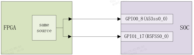
    1. The topology diagram of the GPIO trigger signal is shown in Figure 1. The trigger signal comes from the same signal source of the FPGA. The peripheral connection circuits of the two GPIO pins are completely identical, and edge triggering is used.
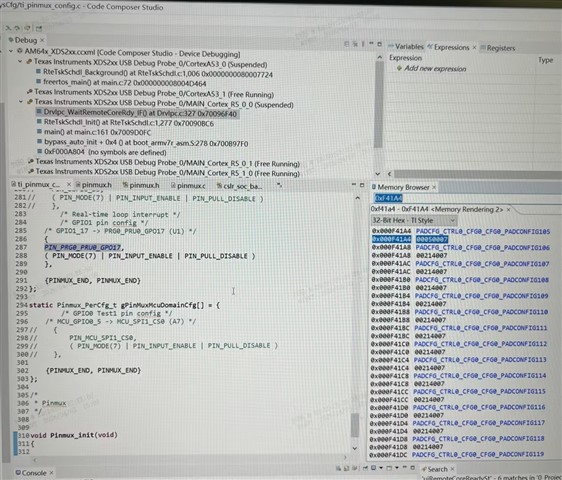
    2. After the program runs, the register values of GPIO1_17 and GPIO0_8 have been checked, both of which are 0x50007 with the 18th bit set to 1, and neither has the receive buffer disabled. Screenshots of the register checks for A53SS0_0 and R5FSS0_0 are shown in Figure 2 and Figure 3 respectively.                                                                                                                                                                                                
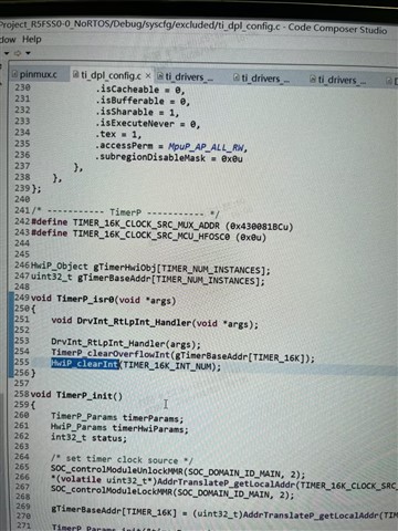
    3. After inspecting the code, it has been confirmed that both the A53SS0_0 core and the R5FSS0_0 core clear interrupts through the Hwip_clearInt function after each interrupt execution is completed. The code screenshot is shown in Figure 4.                                                                              
    Thank you for your reply. Best regards!
  • Are the GPIO1_17 and GPIO0_8 output and input  buffers disabled

    Do you mean output/input buffer the padconfig RX/TX field?

  • Dear TI Expert,
    Here is a supplementary reply to the question “What do you mean under - the interrupt initialization of the A53_0 core fails?”:
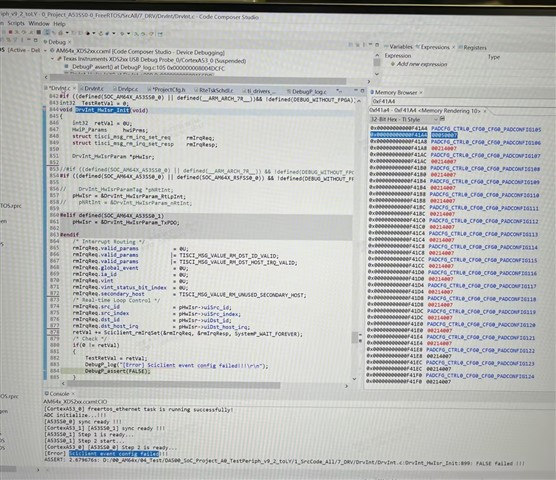
    After completing the interrupt configuration in A53SS0_0, and calling the Sciclient_rmIrqSet function, the return value is -1 instead of 0. This results in the
    print log shown in the figure below, and an assertion is triggered after the printing is finished.

    Thanks

    Best Regards

  • Hello Kevin, Yang, Tony,

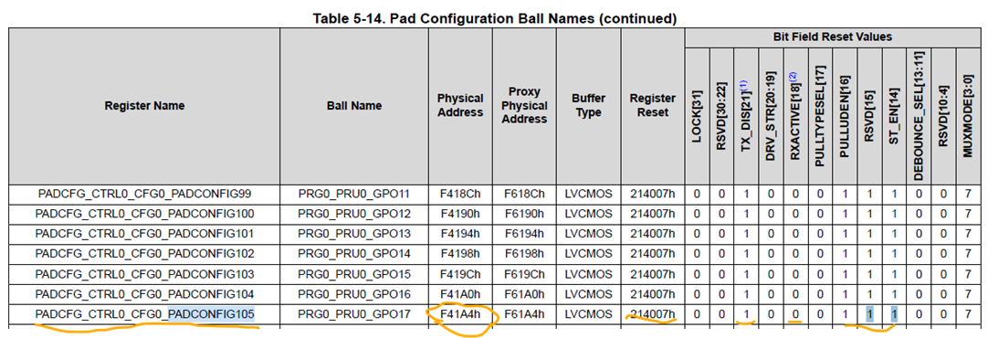
    From AM64x Datasheet, the GPIO1_17 corresponding SoC pin: PRG0_PRU0_GPO17  has the following default pin-mux settings:

    After POR: The input and output buffers are OFF, weak pulls disabled, GPIO1_17 signal selected by default on U1 pin -> the U1 pin shall be HiZ after POR.

    According to the  AM64x TRM, the responsible register is PADCFG_CTRL0_CFG0_PADCONFIG105 at physical address = 0x000F41A4 (matches your used address).

    In your case its register value was changed to 0x00050007:

    PADCFG_CTRL0_CFG0_PADCONFIG105[31:20] = 0x0 -> TX_DIS=0 -> Output buffer enable/disable depends on the GPIO IP itself  - seems like TX_DIS was cleared  in a previous running program or your app.

    [19:16]=0x5  -> Input buffer is enabled (RX_ACTIVE=HIGH), weak pull down enabled, [15:0] = 0x7 -> Schmitt Trigger is disabled (is this intentionally done ?), MuxMode=0x7 -> Q: Does the value = 0x00050007 reflects the state of the padconfiguration105  register during your interrupt setup ?

    From AM64x Datasheet, the GPIO0_8 corresponding SoC pin: OSPI0_D5 seems to has the following default pin-mux settings:

    After POR: The input and output buffers are OFF, weak pull disabled, GPIO0_8 signal selected by default on P20 pin -> the P20 pin shall be HiZ after POR.

    According to the  AM64x TRM, the responsible register is PADCFG_CTRL0_CFG0_PADCONFIG8 at physical address = 0x000F4020 (matches your used address).

    In your case its register value was set to 0x00050007:

    PADCFG_CTRL0_CFG0_PADCONFIG105[31:20] = 0x0 -> TX_DIS=0 -> Output buffer enable/disable depends on the GPIO IP itself   - seems like TX_DIS was cleared  in a previous running program or your app.

    [19:16]=0x5  -> Input buffer is enabled (RX_ACTIVE=HIGH), weak pull down enabled, [15:0] = 0x7 -> Schmitt Trigger is disabled (is this intentionally done ?), MuxMode=0x7 -> Q: Does the value = 0x00050007 reflects the state of the padconfiguration8  register during your interrupt setup ?

    Yang,

    In the particular case when both GPIO pins are tied-off together, and SoC pin output buffers are enabled, there is a possibility of spurious interrupts triggering. If the GPIO1_17 IP output and its Soc pin output are enabled (as it is in your case), flipping the GPIO1_17 OUTPUT_DATA value can cause the other GPIO input to see a pulse transition and detect an undesired interrupt event. Also if  FPGA output is initially to a HiZ, because AM6442 is initialized before it, I would recommend to use external 10k pull resistors at the AM6442 GPIO input pins to avoid spurious interrupt triggering. Select the pull type to match the initial level corresponding to the triggered edge event (PD for rising edge, PU for falling edge). 

    I can suggest the following steps:

    To start, you can first revisit the AM6442 TRM,  Section, 12.1.2.5 GPIO Programming Guide

    1. To be on the safe side, set TX_DIS = HIGH for both GPIOs to force SoC pins output buffers OFF (HiZ).

    2. Make sure to set RX_ACTIVE bitfields for GPIO1_17 and GPIO0_8 pins at  LOW , to disable input buffers before setup of the IRQs.

    3. At the GPIO controller IP level, make sure that  the GPIO1_17 and GPIO0_8 direction is set as INPUT (DIR=1).

    4. Taking into account you enabled a weak pull-down on both GPIO inputs, can you confirm the edge trigger type for the interrupts is " Rising" edge ? 

    You can keep weak pulls disabled in case you  use external stronger 10k pull resistors. 

    5. SET the trigger edges to "rising" to enable the IRQs.

    6. Clear the interrupt status flags.

    7. Set RX_ACTIVE back to HIGH to enable inputs.

    I hope this can help to find the root cause.

    I will follow up on the topic during the next week.

    Thank you !

    Best Regards

    Anastas Yordanov 

  • Hello Yang,

    I would like to apologize for my delayed response !

    Did you manage to find some resolution already for an accurate GPIO1_17 and GPIO0_8 interrupt inputs initialization ?

    Let me know in case it is solved and we shall close the thread.

    If this was NOT the case, please elaborate with more info  on the asked questions. 

    Looking forward to your feedback !

    Best Regards

    Anastas Yordanov

  • Hi Anastas,

    Thanks for your kind support, we have checked with customer that they have solved this problem, so we will close this thread for now. If there is anything else required in the future we will reopen or start a new thread.

    Thanks,

    Kevin