This thread has been locked.

If you have a related question, please click the "Ask a related question" button in the top right corner. The newly created question will be automatically linked to this question.

AM4378: MMC switching characteristics parameter

Part Number: AM4378

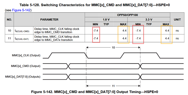
Is the Figure 5-142 parameter 10 and 10 reference point wrong?

I think the CMD and DATA change point should be ahead of the falling clock edge.
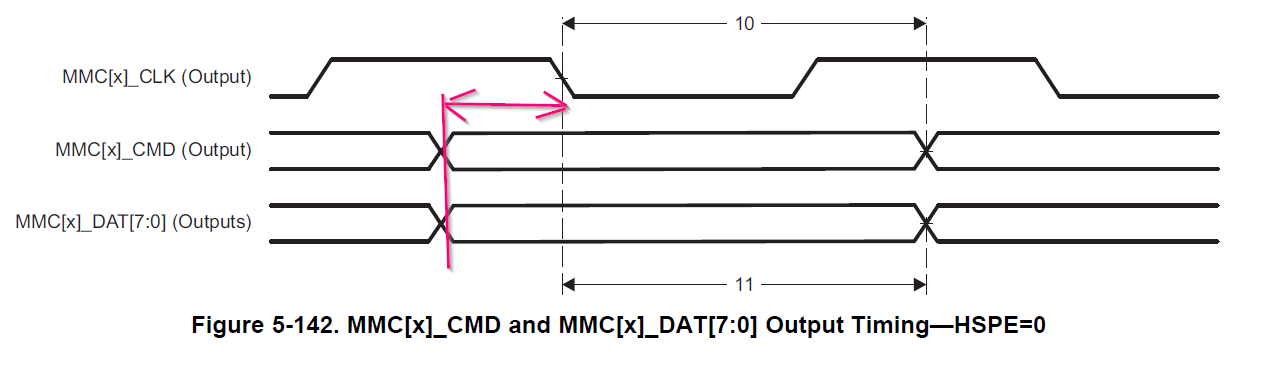
image.png

Figure 5-143 should be below, the data/cmd change point should not over the next clock edge

2026_04_09_13_47_38_am4378.pdf_Adobe_Acrobat_Reader_32_bit_.png

  • This is the official timing diagram from documentation, if you find any discrepancies/questioning and only after your verification/internal tests are suggesting such issue, please file internal JIRA for Engineering to come over and suggest another reading, 

  • Hi Tony,

    About the figures, yes I agree they are not perfect but they must be referenced strictly with their respective tables:

    Note the negative delay is existing along with the positive one, therefore you are right for the case the delay is negative.

    Regards,

    Stan

  • The waveforms simply show which clock edge is being used as the timing reference for the DAT/CMD signal transition. It is not possible to draw a single waveform that represents both cases, where some operating conditions has DAT/CMD signals transitioning before the clock edge and other operating conditions has DAT/CMD signals transitioning after the clock edge. Therefore, we define negative delay values to indicate the DAT/CMD signals can transition before the clock edge.

    As Stan pointed out in his reply, the complete range of delay values need to be considered to determine the actual position of DAT/CMD signal changes relative to the respective clock edge. 

    Regards,
    Paul

  • In order to make it clear, compare it with the correct waveform on AM62x datasheet.

    I knew the negative means CMD/data transit before clock edge, so I didn't question it.

    My question is: The Transition of CMD/data should not span to next clock edge on the waveform, it is the next CMD/data transition point, and it is hold time of current data, not setup time.

    Below mmc waveform are from AM62x datasheet.

  • I agree the waveform is not drawn to scale, where the transition of the DAT/CMD signals should occur before the next rising edge of clock. However, you can see that this relationship is not possible when you compare the minimum clock period value to the DAT/CMD maximum delay values.

    The minimum clock period is 20.8ns, which means there is at least 10.4ns of delay from the falling edge of clock to the next rising edge of clock. The maximum DAT/CMD delay is 4.4ns. Therefore, it is not possible for the DAT/CMD transition to occur after the rising edge of clock, which is used by the attached device to capture the state of DAT/CMD.

    Ignore the scale of the waveform. Only use it to understand which clock edge is being used as the timing reference and use the parameter values to determine the actual timing relationship between clock and DAT/CMD signals.

    Regards,
    Paul