This thread has been locked.

If you have a related question, please click the "Ask a related question" button in the top right corner. The newly created question will be automatically linked to this question.

AM623: Am623 ethernet issue

Part Number: AM623
Other Parts Discussed in Thread: DP83848K

In our project we are using processor AM6231AKGGHHALW and ethernet phy DP83848KSQ/NOPB. 

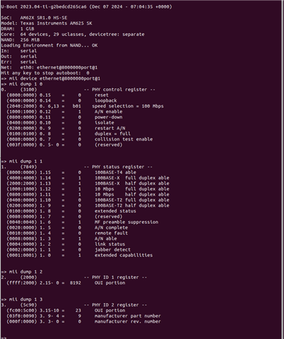
 We are facing a etheret problme sometimes with some boards. During the problem u-boot will give this error message
In this time Reading phy register with u-boot mii command giving ffff result


And in linux 

root@user1-                :/sys/devices/platform/bus@f0000/8000000.ethernet/net/eth0# cat carrier
cat: read error: Invalid argument

And it is showing
Configuring network interfaces... RTNETLINK answers: No such device

Some board the issue is permanant. and in some board it is comming after 3 time reboot or 5 time reboot and it is very random nature. some time it is working.


the device tree and schematic added below (u-boot side)

    main_mdio1_pins_default: main-mdio1-default-pins {
        pinctrl-single,pins = <
            AM62X_IOPAD(0x160, PIN_OUTPUT, 0) /* (AD24/V17) MDIO0_MDC */
            AM62X_IOPAD(0x15c, PIN_INPUT, 0) /* (AB22/U16) MDIO0_MDIO */
        >;
    };

    rmii1_pins_default: rmii1-default-pins {
        pinctrl-single,pins = <
            AM62X_IOPAD(0x0130, PIN_INPUT, 1) /* (AE19) RGMII1_TXC.RMII1_CRS_DV */
            AM62X_IOPAD(0x0148, PIN_INPUT, 1) /* (AD17) RGMII1_RXC.RMII1_REF_CLK */
            AM62X_IOPAD(0x014c, PIN_INPUT, 1) /* (AB17) RGMII1_RD0.RMII1_RXD0 */
            AM62X_IOPAD(0x0150, PIN_INPUT, 1) /* (AC17) RGMII1_RD1.RMII1_RXD1 */
            AM62X_IOPAD(0x0144, PIN_INPUT, 1) /* (AE17) RGMII1_RX_CTL.RMII1_RX_ER */
            AM62X_IOPAD(0x0134, PIN_OUTPUT, 1) /* (AE20) RGMII1_TD0.RMII1_TXD0 */
            AM62X_IOPAD(0x0138, PIN_OUTPUT, 1) /* (AD20) RGMII1_TD1.RMII1_TXD1 */
            AM62X_IOPAD(0x012c, PIN_OUTPUT, 1) /* (AD19) RGMII1_TX_CTL.RMII1_TX_EN */
            AM62X_IOPAD(0x0178, PIN_OUTPUT, 7) /* (AC20) GPIO1_0 */
            AM62X_IOPAD(0x01f0, PIN_OUTPUT, 5) /* (A18) EXT_REFCLK1.CLKOUT0 */
        >;
    };

&cpsw3g {
    pinctrl-names = "default";
    pinctrl-0 = <&rmii1_pins_default>;
    assigned-clocks = <&k3_clks 157 20>;
    assigned-clock-parents = <&k3_clks 157 21>;
};

&cpsw_port1 {
    phy-mode = "rmii";
    phy-handle = <&cpsw3g_phy1>;
};

&cpsw_port2 {
    status = "disabled";
};

&cpsw3g_mdio {
    status = "okay";
    pinctrl-names = "default";
    pinctrl-0 = <&main_mdio1_pins_default>;

    cpsw3g_phy0: ethernet-phy@0 {
        status = "disabled";
    };

    cpsw3g_phy1: ethernet-phy@1 {
        reg = <1>;

        ti,rx-internal-delay = <0>;
        ti,tx-internal-delay = <0>;

        reset-gpios = <&main_gpio1 0 GPIO_ACTIVE_LOW>;
        reset-assert-us = <25>;
        reset-deassert-us = <60000>;
    };
};
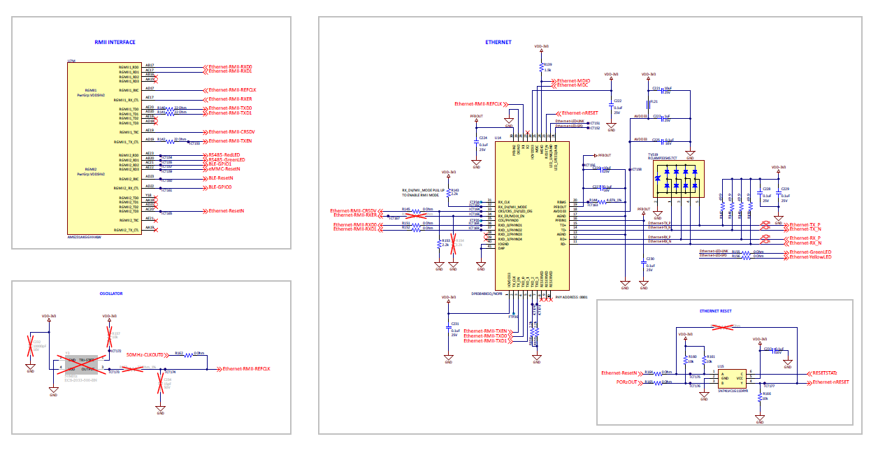

image.png

We have two type of boards development and production version and in developemnt board we didt face issue much but it frequently showing in production version of the board


Is this issue is related to following MDIO errdata
   

  • Hello Jomon Thomas,

    In our project we are using processor AM6231AKGGHHALW and ethernet phy DP83848KSQ/NOPB. 

     We are facing a etheret problme sometimes with some boards. During the problem u-boot will give this error message

    Thank you for the query.

    Can you please elaborate the above.

    Number of boards tested vs no of boards that has issue, number of times tested vs number of times issue seen.

    Regards,

    Sreenivasa

  • Hello Jomon Thomas,

    Can you please share the schematic in a searchable PDF.

    You can share the same over private chat.

    Regards,

    Sreenivasa

  • If you don’t mind, could you please share your email address for sharing the document?

  • Hello Jomon Thomas,

    Please send a hi message and later you can share the info securely.

    Regards,

    Sreenivasa

  • Hello Jomon Thomas,

    I received the schematics through Dhruva Kashyap

    Please make the below changes and do a check.

    C234 - add a 10K pulldown using the cap pads
    R160 - DNI

    Regards,

    Sreenivasa

  • Hi,
    We have tried this change, but the issue is still not solved.

  • Hello Jomon Thomas,

    Thank you.

    Please continue to retain the changes.

    Can you please capture the reset and the clock waveform.

    Regards,

    Sreenivasa

  • Hello Jomon Thomas,

    Can you confirm the issue is observed only during power cycle and the EPHY teset.

    Regards,

    Sreenivasa

  • Hello Jomon Thomas,

    Some board the issue is permanant. and in some board it is comming after 3 time reboot or 5 time reboot and it is very random nature. some time it is working.

    Please elaborate what you mean by permanent - occurs every time after reboot.

    Reboot - does this mean power-cycle or software reboot?

    Regards,'

    Sreenivasa

  • Hi,
    Ethernet initialization issue happening on 10/30 boards intermittently, these units recover after multiple reboots and goes back to the same state eventually after few reboots.

    And this happens on both power cycle and software reboot (by linux "reboot" command or u-boot "reset" command) as well.

  • Hello Jomon Thomas,

    I do not see any bulk caps used for the EPHY.

    Can you help me confirm if the EPHY has been reviewed by TI?

    Regards,

    Sreenivasa

  • Hi,
    Please find the below details

    Item Date Review PCBA Name Comment Owner Comment Action Owner Action Taken
              ETHERNET Page    
      7-10-24 Schematic NA TI Comments Refer below for implementation https://www.ti.com/tool/TIDA-00207   Same is followed
      7-10-24 Schematic NA TI Comments Populate r153 SFO Schematics updated.
      7-10-24 Schematic NA TI Comments Provision to isolate one of the reset status output
    Add 0R and pull up for both inputs and populate as required
    SFO Schematics updated.
      7-10-24 Schematic NA TI Comments pulldown the EPHY reset input SFO Schematics updated.
      7-10-24 Schematic NA TI Comments add bulk cap to the supply pin Connect supply through ferrite SFO Ferrite added for VDD_3V3 supply rail.
      7-10-24 Schematic NA TI Comments Route clock as point to point  add a dual buffer Take note of the buffer placement   Refer schematics checklist SFO Yes considered during PCB design
      7-10-24 Schematic NA TI Comments move cap after R SFO Schematics updated.
  • Hello Jomon Thomas,

    Thank you.

    Refer below for implementation https://www.ti.com/tool/TIDA-00207

    Can you please point me to the bulk capacitors for IOVDD3V3 supply

    Regards,

    Sreenivasa

  •  Hello Jomon Thomas,

    Route clock as point to point  add a dual buffer Take note of the buffer placement   Refer schematics checklist SFO

    Yes considered during PCB design

    In the schematic i have, the processor clock output connects to the SOC RMII input and the EPHY without a buffer.

    This is likely to affect the functionality.

    Can you confirm the revision of the schematics you have for me check with the schematic i have.

    Regards,

    Sreenivasa

  • U15 ANDing logic representation is confusing. Use 3 input AND gate symbol.

    Please do the following 

    DNI 165
    populate R161

    Disable PORz_OUT and use RESETSTATz for resetting the EPHY

    Regards,

    Sreenivasa

  •  Hello Jomon Thomas,

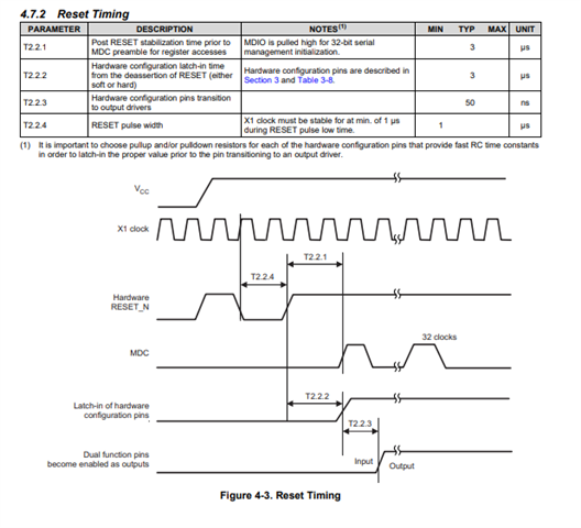
    In the current clock configuration, the clock will be applied after the EPHY is released from reset and this is not recommended.

    The clock is expected to be stable before the reset of the EPHY is released.

    I see you have Y3 provision. Can you populate Y3 and DNI the EXT_REFCLK1 clocking option.

    Alternatively, you need to change R161 (pullup for the SOC IO configured as EPHY reset) pullup configuration to pulldown and release the reset of the EPHY after the clock is configured.

    Regards,

    Sreenivasa

  • Hello Jomon Thomas,

    Please continue to retain the changes.

    Can you please capture the reset and the clock waveform.

    The clock is expected to be available before the reset is released (goes high).

    I suspect this may be reverse in the current board configuration.

    Regards,

    Sreenivasa

  • Hello Jomon Thomas,

    Please refer the EPHY reset release timing 

    Regards,

    Sreenivasa

  • Hello Jomon Thomas,

    The series resistor for 50MHz-CLKOUT0 is 0R in the initial revision and 33R in the latest revision. 

    The clock output (LVCMOS) is a 60R impedance and a 33R added can increase the slew of the clock.

    Can you reduce the series resistor to 0R and perform a check.

    Regards,

    Sreenivasa

  • Hello Jomon Thomas,

    Can you compare the clock skew with the 33R and 0R series resistors.

    Regards,

    Sreenivasa

  • Hello Jomon Thomas,

    Checking if you have been able to make progress.

    Please compare the clock slew of the working board and non-working board 

    Regards,

    Sreenivasa

  • Hello Jomon Thomas,

    I assume the pulldown for the clock input (SOC and EPHY) and the PORz_OUT series resistor connecting to AND gate is DNI and the pullup near the ANDing logic on the PORz_OUT signal is high.

    Regards,

    Sreenivasa

  • Hello Jomon Thomas,

    based on the waveform received i see the clock coming up 10 seconds after the reset is released.

    In the software, can you pull the SOC IO connected to the ANDing logic low after boot and make it high after the clock is configured with a delay of few uS to avoid EPHY seeing any clock glitch.

    Regards,

    Sreenivasa

  • Hi,

    In the code side we using following ti linux setup. 

    Yocto version: kirkstone
    Linux kernel version:  6.1.119-ti
    u-boot: U-Boot 2023.04-ti

    And we using following ti linux drivers for the ethernet ( the same enabled in the u-boot also but not using in actual application)

    CONFIG_TI_DAVINCI_MDIO
    CONFIG_TI_K3_AM65_CPSW_NUSS
    CONFIG_PHY_TI_GMII_SEL


    Please find the below linux ethernet side device tree.

    main_mdio1_pins_default: main-mdio1-pins-default {
    pinctrl-single,pins = <
    AM62X_IOPAD(0x160, PIN_OUTPUT, 0) /* (AD24/V17) MDIO0_MDC */
    AM62X_IOPAD(0x15c, PIN_INPUT, 0) /* (AB22/U16) MDIO0_MDIO */
    AM62X_IOPAD(0x0178, PIN_OUTPUT_PULLUP, 7) /* (AC20) GPIO1_0 */
    >;
    };
    
    main_rmii1_pins_default: main_rmii1-default-pins {
    pinctrl-single,pins = <
    AM62X_IOPAD(0x0130, PIN_INPUT, 1) /* (AE19) RGMII1_TXC.RMII1_CRS_DV */
    AM62X_IOPAD(0x0148, PIN_INPUT, 1) /* (AD17) RGMII1_RXC.RMII1_REF_CLK */
    AM62X_IOPAD(0x014c, PIN_INPUT, 1) /* (AB17) RGMII1_RD0.RMII1_RXD0 */
    AM62X_IOPAD(0x0150, PIN_INPUT, 1) /* (AC17) RGMII1_RD1.RMII1_RXD1 */
    AM62X_IOPAD(0x0144, PIN_INPUT, 1) /* (AE17) RGMII1_RX_CTL.RMII1_RX_ER */
    AM62X_IOPAD(0x0134, PIN_OUTPUT, 1) /* (AE20) RGMII1_TD0.RMII1_TXD0 */
    AM62X_IOPAD(0x0138, PIN_OUTPUT, 1) /* (AD20) RGMII1_TD1.RMII1_TXD1 */
    AM62X_IOPAD(0x012c, PIN_OUTPUT, 1) /* (AD19) RGMII1_TX_CTL.RMII1_TX_EN */
    AM62X_IOPAD(0x01f0, PIN_OUTPUT, 5) /* (A18) EXT_REFCLK1.CLKOUT0 */
    >;
    };


    &cpsw3g {
    pinctrl-names = "default";
    pinctrl-0 = <&main_rmii1_pins_default>;
    status = "okay";
    assigned-clocks = <&k3_clks 157 20>;
    assigned-clock-parents = <&k3_clks 157 21>;
    };


    &cpsw_port2 {
    status = "disabled";
    };


    &cpsw_port1 {
    phy-mode = "rmii";
    phy-handle = <&cpsw3g_phy1>;
    status = "okay";
    };


    &cpsw3g_mdio {
    status = "okay";
    pinctrl-names = "default";
    pinctrl-0 = <&main_mdio1_pins_default>;


    cpsw3g_phy1: ethernet-phy@1 {
    reg = <1>;
    
    ti,rx-internal-delay = <0>;
    ti,tx-internal-delay = <0>;
    
    reset-gpios = <&main_gpio1 0 GPIO_ACTIVE_LOW>;
    reset-assert-us = <25>;
    reset-deassert-us = <60000>;
    
    status = "okay";
    };
    };


    The timing and reset are handled by the ti ethernet drivers directly ( TI_DAVINCI_MDIO and K3_AM65_CPSW_NUSS ). and the timing and pins configurations are provided using the above device tree

    During bootup time the booting flow is reset->tiboot3->tispl->u-boot-> linux ->linux drivers

  • Hello Jomon Thomas,

    Thank you. I need to check with a software expert.

    Can you help me understand if this function is used somewhere in the flow

    cpsw3g_phy1: ethernet-phy@1 {
    reg = <1>;
     
    ti,rx-internal-delay = <0>;
    ti,tx-internal-delay = <0>;
     
    reset-gpios = <&main_gpio1 0 GPIO_ACTIVE_LOW>;
    reset-assert-us = <25>;
    reset-deassert-us = <60000>;
     
    status = "okay";
    };

    Suggestion
    Make the GPIO used for reset low until the 50M clock is configured
    Make the GPIO high (release from reset) after few us delay.

    Regards,
    Sreenivasa

  • Hi,

    Can you help me understand if this function is used somewhere in the flow

    Make the GPIO used for reset low until the 50M clock is configured

        Currently, this is handled by the TI Linux drivers. Can you suggest which driver I need to modify for this?

  • Hello Jomon Thomas,

    Thank you.

    Currently, this is handled by the TI Linux drivers. Can you suggest which driver I need to modify for this?

    I  need to assign the query to a software expert.

    Can you start a new thread to continue the hardware discussion on the thread.

    You can reference this thread in the new thread.

    Regards,

    Sreenivasa

  • Hello Jomon Thomas,

    Can you please confirm if you had a chance reduce the series resistor value to 0R and perform some tests.

    Regards,

    Sreenivasa

  • Hi,

    We have changed the series resistor to 0Ω, and now it seems to be working. Further testing with another board is ongoing. Thank you for your valuable support

  • Hello Jomon Thomas,

    Thank you for the note and good to hear the progress.

    I still need you to capture the waveform on the reset and clock since there is a violation of the sequence.

    We should be able to hold the EPHY in reset until the clock is configured by software change and adding a pulldown on the 50M clock input.

    Regards,

    Sreenivasa

  • Hi,

    Please suggest how to proceed with the software changes. Currently, we are using the official TI Linux drivers.

  • Hello Jomon Thomas,

    As suggested before, please start a new thread for the software team to support and we can continue the hardware related discussion on this thread.

    Regards,

    Sreenivasa

  • Hello Jomon Thomas,

    Thank you.

    The thread will be supported by the software applications team.

    Regards,

    Sreenivasa

  • Hello Jomon Thomas,

    Based on the discussion, today here are the likely changes for releasing the reset after the clock is stable.

    Common change 

    Disconnect PORz_OUT - this is redundant in the current design - DNI R165. Ensure R160 is populated.

    Changes for EPHY reset implementation using processor GPIO Ethernet-ResetN

    Preferred approach 

    Change R161 pullup to pulldown (this needs to be a glue wire in this case)

    The pulldown ensures the EPHY is reset. In the code in case the Ethernet-ResetN  is being configured configure as low.

    The EXT_REFCLK1 can be configured for 50MHz clock output and the Ethernet-ResetN  can be made high.

    Advantage: The EPHY reset will be low from power-up until the clock is enabled and the software sets the Ethernet-ResetN  high. No reset glitch

    Alternate approach for testing 

    Configure Ethernet-ResetN low during the boot as early as possible. This will cause the reset to glitch High to low.

    The EXT_REFCLK1 can be configured for 50MHz clock output and the Ethernet-ResetN  can be made high.

    Nite: The above changes can solve the reset timing related issue.

    Regards,

    Sreenivasa 

  • Hi,

    A discussion is ongoing with the software technical team regarding the implementation of the reset procedure. In the driver, I can see that a software reset is being triggered, but I am still investigating the GPIO pin-level reset


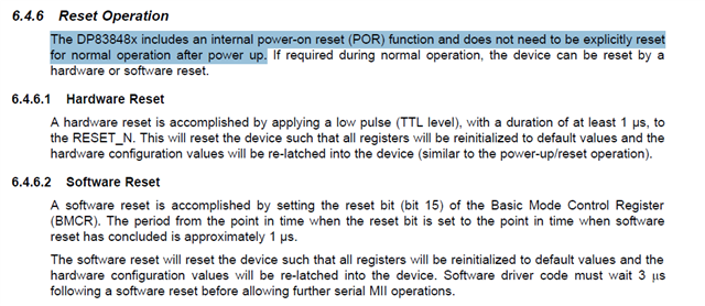
    Also, the screenshot below is from the DP83848K datasheet. May I know your opinion on this? It mentions that it ‘does not need to be explicitly reset for normal operation after power-up

  • Hello Jomon Thomas,

    Thank you.

    Please note the issue we are resolving is the clocking issue and not the reset issue.

    The above section assumes the design to follow the recommended clocking + reset sequence.

    When the required reset sequence is followed, there is no need to perform another reset but does not stop you from doing the reset. 

    The pin strapping in case connected to the processor may be affected and hence the note.

    Regards,

    Sreenivasa

  • Hi All, 

    Capturing the discussion here for tracking.

    I suspect the discussion here is on improving the performance vs right/wrong.

    I wanted to be sure that TI is making recommendation to ensure optimal signal integrity as well as proper communication performance. I do not know the use case and so you can judge the best.


    You may be able to route the clock without buffering but will need careful routing as well as timing analysis to ensure signal integrity. It is the board designer responsibility that the routing works over temperature and voltage variations.


    Connecting clock to x2 loads without buffer

    It is never a good idea to connect to two clock inputs to a single clock source.  This is very likely to cause signal integrity issues for one or both devices.  There may be cases where this can be done with careful PCB layout that was simulated and the PCB layout of the clock signal optimized for signal integrity, but this is very risky. one source to two load connection topology is not a recommended topology for a clock signal and needs to be fixed

    As per the datasheet, the CLKOUT0 pin is capable of driving both the external RMII PHY and the RMII[x]_REF_CLK pin, and no clock buffer is recommended. The schematic design has been implemented in accordance with the datasheet recommendations.

    Data sheet is describing the required connections. Data sheet does not any time provide custom board design implementation approach or recommendations.

    In the user guidelines, CLKOUT0 is buffered output even though additional external buffer is recommended. It is not a mandatory requirement. Right?

    I suspect you may have been confused with buffering. Buffering of the clock output means clock input to the SOC RMII refclock and the EPHY is expected to be connected through individual buffers. Refer below

    https://www.ti.com/lit/ug/sprado3b/sprado3b.pdf

    7.4.1.1.4.3 Processor Clock Output (CLKOUT0)

    When EPHY is configured as a device, the MAC and the EPHY uses a 50MHz common clock that is synchronous to both transmit and receive data. The 50MHz clock is defined in the RMII specification as a common data transfer clock signal that is used by both the MAC and the EPHY, where transitions are expected to arrive simultaneously at the MAC and EPHY device pins. The common clock provides better timing margin for both transmit and receive data transfers. Important requirement is that the MAC and EPHY do not receive any non-monotonic transitions on the clock inputs. To control the clock signal integrity, the recommendation is to route the common clock signal through a single input, two-output phase aligned buffer. The recommendation is to use equal length signal traces that are half the length of the data signals for connecting the clock buffer outputs, where one clock output connects to the MAC and the other connects to the EPHY.

    Regards.

    Sreenivasa

  • Hello Jomon Thomas,

    During the call we discussed about capturing the expanded clock waveform with 0R and 33R.

    We also discussed measuring the trace length from the series resistor to EPHY and the SOC RMII reference clock input.

    Please share the waveforms.

    Regards,

    Sreenivasa

  • Hello Jomon Thomas,

    Checking if you have been able to make progress.

    I assume you understand the software fix is only for the boards built.

    Below is the recommended solution for the clock to be available before the reset is released

    A pull-down is recommended to be placed on the Ethernet-ResetN signal rather than a pull-up.  This way the PHY would remain in reset until software has time to initialize AM62x pin A18 sourcing the Ethernet-RMII-REFCLK signal and AM62x pin AC20 sourcing Ethernet-ResetN signal. Software would initialize the clock source from AM62x pin A18, delay at least as long as the PHY datasheet says the clock needs to be valid before releasing reset, then drive the reset signal high from AM62x pin AC20."

    Regards,

    Sreenivasa

  • Hi,

    We will check the pull down possibility.

    I would like to add a few observations, although I’m not sure how helpful it is. We disconnected the 50 MHz clock source from the PHY chip by removing R162. Then, we attempted to access the MDIO registers from U-Boot, and it worked - we were able to successfully read the PHY ID register and other registers. I assumes RMII communication will not work with 50Mhz clock but at least MDIO is responding with out this clock.

  • Hello Jomon Thomas,

    Thank you.

    MDIO interface does not have 50MHz (or 25MHz) clock dependency in the custom board use case.

    When you disable the clock, you are not violating the timing of the EPHY and so the EPHY does not internally go into an unexpected state during power-cycle and likely works.

    Regards,

    Sreenivasa