Part Number: AM623
Dear members,
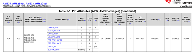
I would like to better understand the meaning of “PAD” as used in the DSIS / pin descriptions of TI devices (specifically during boot or reset).
Could someone please explain what PAD implies electrically, and what should be considered during the schematic and PCB design phase when a pin is marked as PAD (e.g., pull‑up/down requirements, whether it can be left floating, and how it is sampled)?
Any clarification or references would be greatly appreciated.
Best regards,
Farzaneh