This thread has been locked.

If you have a related question, please click the "Ask a related question" button in the top right corner. The newly created question will be automatically linked to this question.

TMS320F28069M: TMS320F28069M can not start up

Part Number: TMS320F28069M

Hi TI,

I designed a PCBA to test programming of TMS320F28069MPZT, but MCU can't start up.

The XRS pin pull low every 13.45 ms after I provide 3.3V from power supply.

I also did some modifications below according to datasheet and EVM after I reviewed my design. It still not working.

  1. pin 46 VDD3VFL, connect to 3.3V, add 0.1uF
  2. pin 60 X1, tie to GND or open according to EVM
  3. pin 27 VREFLO, tie to GND
  4. pin 90 VREGENZ, tie to GND

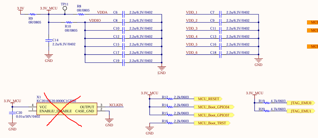
Please help check my schematic.
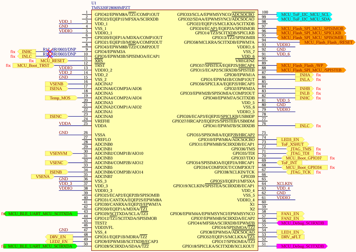
image.png

image.png

  • Hi,

    The XRS pin pull low every 13.45 ms after I provide 3.3V from power supply.

    Are you able to connect to the device ?

    The above images look okay, did you try to bring up the MCU based on INTOSC without XCLKIN ?

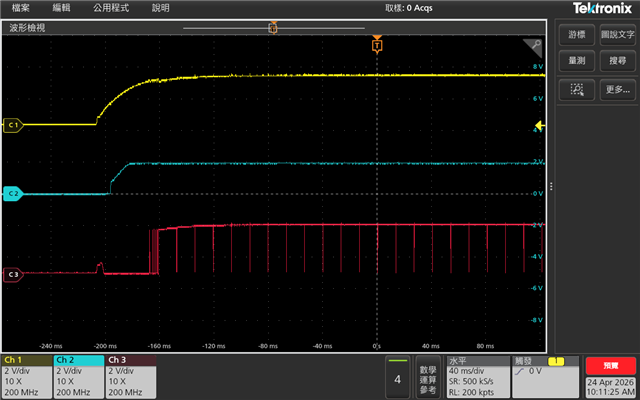
    Can you share the scope shot of  VDD, VDDIO and XRSn at power up and subsequent XRSN triggers ?

    Thanks

  • Hi Prarthan,

    Do you mean connect the MCU by JTAG ot debug tool? No, I didn't use any tool to bring up my PCBA.

    I would like to bring up the MCU based on INTOSC first, maybe XCLKIN in the future.

    Here is my screen shot from scope.

    C1: 3.3V_MCU (VDDIO), C2: VDD_3 (VDD), C3: XRSn

    VDD_1~6 are the same.

  • Do you mean connect the MCU by JTAG ot debug tool? No, I didn't use any tool to bring up my PCBA.

    Can you try connecting to MCU using debugger ?

    1: 3.3V_MCU (VDDIO), C2: VDD_3 (VDD), C3: XRSn

    VDD_1~6 are the same.

    The Vddio is 3.3V ? VDD looks to be okay at 1.8V.

    Have you tried supplying the VDDIO and VDD both externally ? Internal voltage regulator (VREG) enable with internal pulldown. Tie directly to VSS (low) to enable the internal 1.8-V VREG. Tie directly to VDDIO (high) to disable the VREG and use an external 1.8-V supply

    What is the XRSn pin connection on board ? Is it pulled up to VDDIO ?  A resistor with a value from 2.2 kΩ to 10 kΩ should be placed between XRS and VDDIO. If a capacitor is placed between XRS and VSS for noise filtering, it should be 100 nF or smaller

    Thanks