TMDX654IDKEVM: EVM has failed

Part Number: TMDX654IDKEVM

EVM was working fine for 2 weeks. After a power cycle, uBoot failed to initialize memory. COntinuous reboot after that. Request RMA and return. Screenshot 2026-04-29 140307.png


  • Hi,

    is this a single EVM that you have showing this issue or multiple?  

    -James

  • Hi James. We purchased just one of these EVM. We are using it in a Profinet Conformance Test System.

  • Hi Tha Hang,

    Could you please share some info regarding below items,

    1. Have you tried with Linux SDK from the EVM page? https://www.ti.com/tool/PROCESSOR-SDK-AM65X

    2. Could you please share the power supply details that you are currently using?  

    Regards

    Deepak

  • Hi Deepak,

    We have not used the Linux SDK. We used the PII North America ETS test image provided by them. PII North America has standardized on this EVM for their test system and I assume there are quite a few in the field.

    https://www.profibus.com/download/profinet-test-bundle

    The power supply is rated for 12V at 5.8A. Like I mentioned earlier, this board ran without issue for two weeks. After powering cycling, uBoot failed to initialize the DRAM. This leads me to believe their is a DRAM or memory controller failure of some kind.

    Tha had last checked with your business department and they said that the engineers were responsible for evaluating and approving RMAs. 

    We need to due diligence in order to get our product into the compliance lab and not having a working pre compliance system is delaying our Sitara based product entry into the market.

    We would like to get an RMA issued and a new board at the earliest convenience. 

    Best Regards,

    Kent Hartig

    Director of Engineering

    Williamson Corporation

    khartig@williamsonir.com

  • Hi Kent Hartig

    Thanks for the response, would you please try with Linux image from here https://dr-download.ti.com/software-development/software-development-kit-sdk/MD-diW9VClvQJ/11.02.05.02/tisdk-default-image-am65xx-evm-11.02.05.02.rootfs.wic.xz

    If the above is not booting could you please measure the voltage on the below Test points and share the results? 

    Regards

    Deepak

  • Hi Deepak

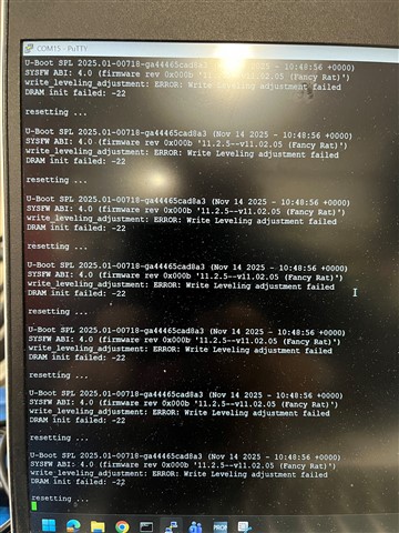
    I put the above image on an SD card and the boot output is shown

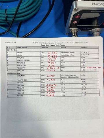
    Measured voltages as you requested in RED. I could not find TP25 on this board.

    You can see that the VDDR_VTT and VPP_1V8 are out of spec.

  • Hi Tha Hang,

    The voltage measurement results pointing to hardware related issue.

    - Can you measure the enable signals S3 and S5 (TP84 ) on the VTT regulator?

    - What's the resistance from VTT rail (TP5) to ground with power OFF?

    - Was the board being used in an ESD-protected environment (ESD mat, wrist strap, etc.)?

    Regards

    Deepak

  • - Was the board being used in an ESD-protected environment (ESD mat, wrist strap, etc.)? YES, all of our surfaces have ESD mats, wrist strap stations and we wear and test heel straps daily. I don't know what good the mat does with the rubber feet on the standoffs.

    WRT to TP5. Resistance is 7.3K ohms.

    WRT to TP84. DC voltage is predominantly 0 volts but it looks like it may be pulsing. I can check with an oscilloscope if you wish.

  • Hi Tha Hang,

    Thank you for sharing the results.

    As per the data provided, the voltage at TP84 is low, but it is expected to be high (3.3V). To help troubleshoot this, could you please check the voltage across R707? Additionally, could you measure the resistance from TP84 to ground while the power is off?

    It is possible that a dry solder joint is affecting the connectivity. If that is the case, a soldering touch-up on U10 pins 7 and 8, as well as U109 pins 8 and 9 may resolve the issue.

    Note: These soldering touch-up should only be performed by qualified personnel.

    Regards

    Deepak

  • Hi Deepak,

    TP84 with power off is 99.2K ohms

    Voltage across R707 is 0.687 volts

    Touched up all pads on both U10 and U109.

    Did not fix the problem.

    Regards, Kent

  • Hi Kent,

    Could you please check with on Oscilloscope below location? also check the resistance across the R707 and share it here?

    1. Probe on R707,

    2. Probe on RESETSTATz TP48, MCU_RESETSTATZ TP38, PORz_OUT TP86, MCU_PORz_OUT TP85

    Also one question? all these measurement are taken without bootable media rt?

    Regards

    Deepak

  • Hi Deepak,

    1. Probe on R707    9.78K ohms

    2.

    RESETSTATz TP48

     MCU_RESETSTATZ TP38

    PORz_OUT TP86  Cannot find test point

    MCU_PORz_OUT TP85

    Also one question? all these measurement are taken without bootable media rt?

    I believe you are asking if the firmware is running when I took these measurements? Yes.

    -Kent

  • Hi Kent,

    Thanks for the Measurement and the results, 

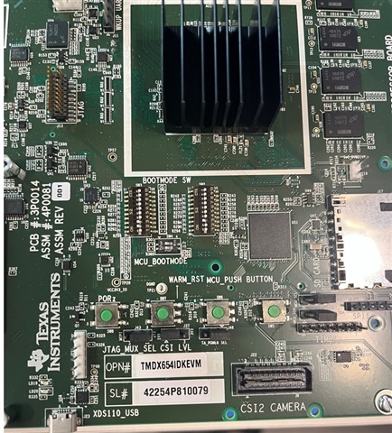
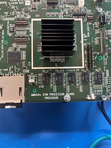
    Could you please share the board details like serial number and Board Revision,? If possible could you please share the image of the board that you are using?

    Also could you please try booting with below image?
    https://dr-download.ti.com/software-development/software-development-kit-sdk/MD-diW9VClvQJ/09.03.05.02/tisdk-default-image-am65xx-evm-09.03.05.02.wic.xz 

    Regards

    Deepak

  • Hi Deepak,

    Images with numbers attached:

    The boot console is the same using the prescribed image.

    Can we get some resolution to this issue?

    Regards, Kent

  • Hi Kent,

    Thanks for sharing the image, I am working with the team,

    Could you please check voltage across R707 without SD card and see its 0v? above you mention that 0.687V is with SD card

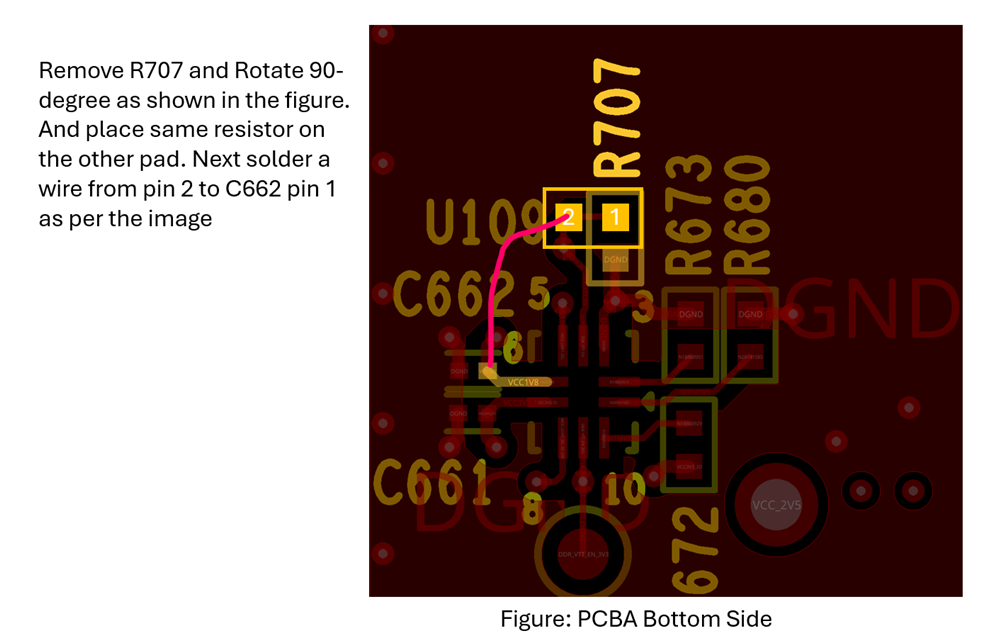
    If its showing 0v without SD card then we can try providing a 10K pull up to VCC1V8 on DDR_VTT_EN net and remove R707 pull down. See below Instruction

    Regards

    Deepak 

  • Hi Deepak,

    Confirmed voltage around R707 is 0V with SD card removed.

    -Kent

  • Hi Kent,

    Thanks for the confirmation, Would you be able to perform above modification?

    Regards

    Deepak 

  • Hi Deepak,

    We can but want assurance that if that doesn't work, we can exchange the board as last resort. We are losing site that we purchased this board to stand up a conformance test system, and we are losing precious time in doing that.

    Regards,

    -Kent

  • Hi Kent,
    I understand the situation and apologize for the inconvenience. However, we may not be able to exchange the board since it was working initially. 
    The impedance measurements appear to be correct, as they nearly match the values from the working board:
    On Working Board
    TP5 = 1.9K ohm
    TP84 = 98.8K ohm
    R707 = 9.79K ohm
    If you can try the previously recommended modification, that is the best approach I can suggest. If that modification does not work, I can suggest another modification to forcefully turn on the VTT Regulator (U10). For that, we would just need to short TP84 to VCC3V3_PREREG (C25.1)
    Regards
    Deepak
  • Hi Deepak,

    Let's discuss the board exchange off line. You can email me at khartig@williamsonir.com.

    Regards, Kent

  • Hello Deepak,

    Well, I guess I am forced to attempt repair on this board. The issue is at TP84 (DDR_VTT_EN_3V3). This voltage is at 0V. This enable appears to drive the VTT enable for the DDR4. In looking at the schematic, I cannot find a driving source other than a 100K pull down at R41. Before I tie that pin to VCC3V3_PREREG, please confirm my assumption that this pin should noy be floating.

    Regards, Kent

  • Hi Kent,

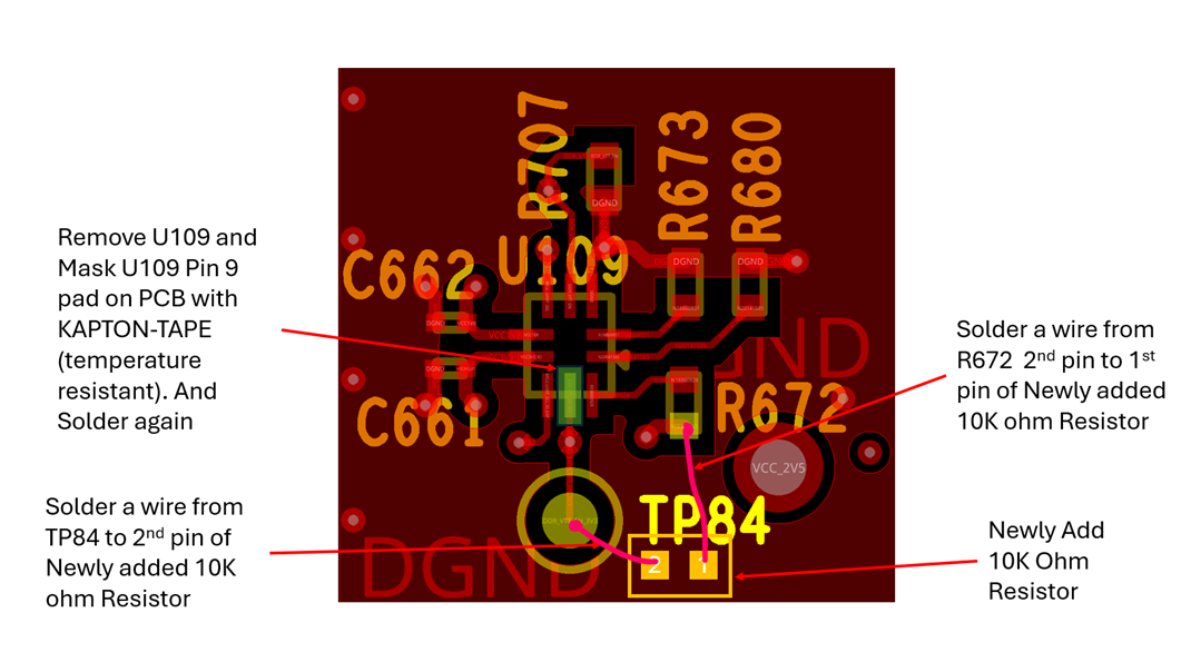
    The SoC is attempting to enable the VTT rail through DDR_VTT_EN_3V3 signal, but the signal is failing to reach the required 1.8V threshold (currently measuring 0.678V across R707). To resolve this loading issue and restore functionality without losing other features, isolate the signal by completing the following rework steps:
    • Remove R41 to isolate the signal line.
    • Remove and replace U109 (the level translator) following standard board rework instructions.
    • Install a new 10 kΩ resistor to pull up the VTT enable signal.


    Thank you for attempting the requested rework. Please ensure your workspace is an ESD-safe environment and the soldering station is properly set up before beginning

    Regards

    Deepak

  • Hi Deepak,

    Would it be as effective to just cut the trace at Pin 9 of U109 to the via connecting to TP84? 

    Regards, Kent

  • Hi Kent,

    Yes, If you are capable of cutting the trace without affecting adjacent layer would be okay. 

    Regards

    Deepak

  • Hi Kent,

    Just curious, were you able to make the modification? Is the board working as expected now?

    Regards

    Deepak

  • Hi Deepak,

    I haven't performed the "surgery" yet. I may get to it on Monday. Will Advise. 

    Regards, Kent

  • Hi Deepak,

    We had a chance to perform the rework. Th DDR_VTT_EN_3V3 at pins 7 and 9 of U10 is a solid 3.3V

    Still reporting the issue in uBoot. Measured voltages around U10:

    C25 - 3.3V

    C22 - 1.28V

    C23 - 3.3V

    C37 - 640mV to 720mV

    The VDDR_VTT looks like it attempts to power on but powers off after a short time. The amplitude of the pulse is 500mV and period is very short.

    Regards, Kent

  • Hi Kent,

    Thanks for sharing the result,

    Could you please explain more about the behavior?

    DDR_VTT_EN_3V3 is 3.3V and seeing same time VDDR_VTT is 0v after short period of time? is it continuously coming pulse's or after power cycle again seeing pulse?

    Also any progress or change in the uBoot output prints? are you seeing continuously repeating the prints same as above previous output?

    And can you confirm once again the resistance across TP5 w.r.t GND on power off. 

    Regards

    Deepak

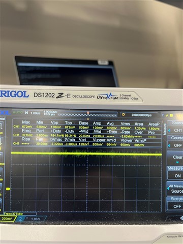
  • Now VDDR_VTT is at a constant output of ~600mV after a power cycle.

    TP5 to DGND is 15.9Kohms at power off.

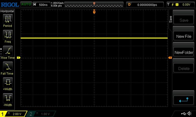
    Same console output as before. Attached console output and scope trace at TP58.

  • Hi Kent,

    Now VDDR_VTT is solid, can you try the above shared linux image one more time?

    Also is it possible you to connecting CCS and try initialize through Gel file?

    What is the temperature of the SoC while running the test?

    Regards

    Deepak

  • Hi Depak,

    Can you share link to the image again and advise U? for SoC you want me to check?

    I have used a GEL file with the Sitara AM57x in the past. Is there a specific procedure for this variant?

    Thanks, Kent

  • Hi Kent,

    Linux image from here https://dr-download.ti.com/software-development/software-development-kit-sdk/MD-diW9VClvQJ/11.02.05.02/tisdk-default-image-am65xx-evm-11.02.05.02.rootfs.wic.xz

    Measure temp on U34,

    Do have the capability to make reduce the DDR clock in uboot and see? 

    Regards

    Deepak

  • Hi Deepak,

    Default image is running. U34 temp at heatsink 95 degrees in 74 ambient.

    How do I slow down the DDR clock via uBoot? Is there a command sequence to issue?

    Thanks, Kent

  • Trying to enter uBoot command prompt from boot. Prints the leveling error, does not allow keyboard input and just continually reboots.

  • Hi Kent,

    We will try DDR initialize through CCS, Please Try to install CCS 12.8.1 Version (https://www.ti.com/tool/download/CCSTUDIO/12.8.1)

    Here below is the link that explain how to connect through CCS. 

    Link:- https://software-dl.ti.com/processor-sdk-rtos/esd/AM65X/09_01_00_02/exports/docs/processor_sdk_rtos_am65xx_09_01_00_02/docs/user_guide/ccs_setup_am65xx.html

    The Gel Files are already available in the CCS installation folder (C:\ti\ccs1281\ccs\ccs_base\emulation\boards\am65x\gel\M4_DDR39SS)

    Once you completed the 6.3.1 step, then next step you have to add the gel file (M4_R5orA53_Startup.gel) to CortexA53_0_0 and save

    Then Launch the target configuration and first connect DMSC then connect CortexA53_0_0 core.

    Observe the console window for the below text.

    "DDR4 Initialization has PASSED!!!!
    DDR is configured for 800MHz operation"

    Note:- 

    Please make sure that you have selected the right board see below FYI

    Regards

    Deepak

  • Hi Deepak,

    Give me a couple of days to do this. It's a background project for me at this point. 

    Thanks, Kent

  • Thanks,

    I will wait to hear back from you, Also is the above 95 degree you mentioned in degree C?

    Regards

    Deepak

  • After running a bit the temp is now 98 degrees F.

  • HI Deepak,

    Had a chance to do this today.

    Here is the CCS console output from the target run:

    DMSC_Cortex_M3_0: GEL Output: Detected Silicon Rev 2.0
    DMSC_Cortex_M3_0: GEL Output: Reconnecting to the M3.
    DMSC_Cortex_M3_0: GEL Output: Nothing to do. AM65xEVM is already configured.
    CortexA53_0_0: GEL Output: VTT Regulator Enabled
    CortexA53_0_0: GEL Output:
    PHY Init complete
    CortexA53_0_0: GEL Output: DDRSS_DDRPHY_PGSR0 = 0x8000000F
    CortexA53_0_0: GEL Output:
    Waiting for DRAM Init to complete...
    CortexA53_0_0: GEL Output:
    DRAM Init complete
    CortexA53_0_0: GEL Output: DDRSS_DDRPHY_PGSR0 = 0x8000001F
    CortexA53_0_0: GEL Output:
    Waiting for write leveling to complete
    CortexA53_0_0: GEL Output:
    Write leveling done
    CortexA53_0_0: GEL Output: DDRSS_DDRPHY_PGSR0 = 0x8000003F
    CortexA53_0_0: GEL Output:
    Write Leveling completed successfully
    CortexA53_0_0: GEL Output:
    Waiting for Read DQS training to complete
    CortexA53_0_0: GEL Output:
    Read DQS training done
    CortexA53_0_0: GEL Output: DDRSS_DDRPHY_PGSR0 = 0x8000007F
    CortexA53_0_0: GEL Output:
    Read DQS training completed successfully
    CortexA53_0_0: GEL Output:
    Waiting for Write leveling adjustment to complete
    CortexA53_0_0: GEL Output:
    Write leveling adjustment done
    CortexA53_0_0: GEL Output: DDRSS_DDRPHY_PGSR0 = 0x808000FF
    CortexA53_0_0: GEL Output: ****ERROR in Write Leveling Adjustment Training****
    CortexA53_0_0: GEL Output: checking Write Leveling Adjustment status per byte...
    CortexA53_0_0: GEL Output:
    DDRSS_DDRPHY_DX0RSR2 = 0x00000000
    CortexA53_0_0: GEL Output:
    DDRSS_DDRPHY_DX1RSR2 = 0x00000000
    CortexA53_0_0: GEL Output:
    DDRSS_DDRPHY_DX2RSR2 = 0x00000001
    CortexA53_0_0: GEL Output:
    DDRSS_DDRPHY_DX3RSR2 = 0x00000000
    CortexA53_0_0: GEL Output:
    DDRSS_DDRPHY_DX4RSR2 = 0x00000000
    CortexA53_0_0: GEL Output:
    DDRSS_DDRPHY_DX0RSR3 = 0x00000000
    CortexA53_0_0: GEL Output:
    DDRSS_DDRPHY_DX1RSR3 = 0x00000000
    CortexA53_0_0: GEL Output:
    DDRSS_DDRPHY_DX2RSR3 = 0x00000001
    CortexA53_0_0: GEL Output:
    DDRSS_DDRPHY_DX3RSR3 = 0x00000000
    CortexA53_0_0: GEL Output:
    DDRSS_DDRPHY_DX4RSR3 = 0x00000000
    CortexA53_0_0: GEL Output:

    ====

    DDR4 Initialization has FAILED!!!!
    DDR is configured for 800MHz operation
    ====

    CortexA53_0_0: GEL Output: DDRSS_DDRPHY_PGSR0 = 0x808000FF

    Regards, Kent

  • Hi Kent,
    Thanks for sharing the result.
    As per the result, the byte 2 datalines are showing errors. If you want to continue working with the same EVM with reduced DDR data bus, we can try reducing the DDR databus width from 32-bit to 16-bit. I can provide you with a gel file to test with the 16-bit bus width if needed.
    Alternatively, we could try replacing one of the DDR chips, though it is uncertain if the processor side is damaged, similar to the VTT enable pin. 

    Regards

    Deepak

  • Hi Deepak,

    At this point, it makes more sense to get another board. Between the 2 of us, we have been spending many man hours and don't have a positive outcome. For these fine pitched devices, I would have to send the board out to our CM to perform the work.

    Regards, Kent

  • Hi Kent,

    I completely understand your concern, Thank you for your time and efforts in investigating this issue. Please feel free to reach out if you have any further questions or need additional assistance.

    Regards

    Deepak