This thread has been locked.

If you have a related question, please click the "Ask a related question" button in the top right corner. The newly created question will be automatically linked to this question.

AM625: Request for Guidance on DTS Customization for SPI and UART Enablement

Part Number: AM625

Dear Team,

I am currently using the BeaglePlay with the image ti-sdk-default-image-rt-beagleplay-ti-12.00.00.07.04.rootfs.wic.

 Based on your earlier guidance, I understand that I need to customize the k3-am625-beagleplay.dts file to enable SPI interfaces.

My requirement is to enable three SPI interfaces and four UART interfaces, and before proceeding, I would like to understand whether enabling these peripherals could affect any existing interfaces or onboard functionalities due to pin-mux or resource conflicts.

I would be very grateful if you could kindly guide me on the proper DTS customization steps, any dependencies or conflicts I should be aware of, and the best practices to safely enable these interfaces without impacting other peripherals. Thank you very much for your support and assistance.


Thanks & Regards
Aparna C Nair

  • Hi Aparna,
    The steps to enable SPI for one, or multiple instances, and similarly for UART remain the same. For UART, do not use instances being used by other peripherals on the board/SoC. Please check the dtsi files for what all instances are available, compare with the beagleplay dts file to check which is available and which is used. Also, check the beagle play schematics on which SPI/UART instances from the SoC are exposed on the board so you can actually use them or can let go of some utility on existing default UART/SPI instances get an instance of UART/SPi for your custom use.

    All pinmuxes are mentioned in the AM62x datasheet: https://www.ti.com/lit/ds/symlink/am623.pdf, for any peripheral you want to use, find the corresponding SoC ball it can be output from, and he check the dts files to check if they are not already being used for some other peripheral. But even if a SoC ball seems free to use for your usecase, you must check if the SoC ball can be accessed on the EVM/board you are using, if not, you'll need a custom board design per your needs.

  • Hello Sir,

    Using the AM62x datasheet, I searched for the AMC ball numbers, but I could not properly correlate them with the information provided in the datasheet.

    Could you please provide the link for the full schematic of the AM62x?

    Also, based on the datasheet and DTS files, I am finding it difficult to understand the pin mapping and configuration. I have attached the UART_TX and UART_RX details from the datasheet for reference. Could you please explain how these are related to the DTS files?

    I can see the pinmux information in the datasheet, but I am unable to identify the corresponding SoC ball numbers and connect them with the DTS entries. Could you please explain in more detail how to interpret the datasheet tables from the perspective of DTS and pinmux configuration?

    Please clarify.

    Thanks and Regards

    Aparna C Nair

  • Hi Aparna,

    Hello Sir

    Divyansh will do.

    Could you please provide the link for the full schematic of the AM62x?

    Schematics are for the board/EVM you are using and not the SoC. Different boards (example BeaglePlay and TI EVM) will have different schematics. Assuming you are using Beagleplay, a trivial google search gives this: https://git.beagleboard.org/beagleplay/beagleplay/-/blob/main/BeaglePlay_sch.pdf?ref_type=heads.

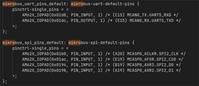
    DTS files and schematics show the following:
     

    The above tells you MikroBus Connector uses UART5 and SPI2.

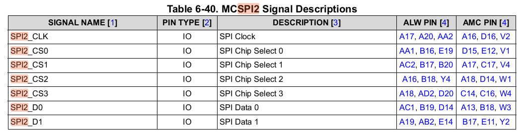
    Now you check the Datasheet for these pins:
    Take SPI2 example:
    Each SPI2 pin can be pinned out via multiple SoC balls as specified in:

    But you need to identify which one your board is using. Let's say SPI2_D0, you can either trace this back on schematics (recommended) or check what's specified in DTS:

    Both will show SPI2_D0 is routed from ball B19.

    Now you check the B19 pinmux in the table:

    Now all these are possible pinmux from B19, make sure the the pin offset 0x0194 (for B19) is not used for any other peripheral that's possible in the pinmux to avoid conflicts..

  • Thank You So Much

  • Hello Sir,

    I need one more clarification regarding the DTS pin configuration format.

    While checking the DTS file, I noticed that the pins are mapped in the following format:

    mikrobus-spi-default-pins {
    pinctrl-single,pins = <0x1b0 0x54001 0x1ac 0x54001 0x194 0x54001 0x198 0x54001>;
    phandle = <0x1d>;
    };

    mikrobus-uart-default-pins {
    pinctrl-single,pins = <0x1d8 0x54001 0x1dc 0x10001>;
    phandle = <0x0e>;
    };

    mikrobus-i2c-default-pins {
    pinctrl-single,pins = <0x1d0 0x64002 0x1d4 0x64002>;
    phandle = <0x1c>;
    };

    However, I could not fully understand how this pin configuration works. Could you please explain how to interpret and understand this configuration format?

    I would also like to understand:

    • From where do we obtain the pin offset values such as 0x1b0, 0x1d8, and 0x1d0?

    • What does the value 0x54001 or 0x64002 represent?

    • How is the phandle value generated, and what is its purpose in the DTS file?

    A detailed explanation would be very helpful.


    Thanks & Regards

    Aparna C Nair
  • Hi Aparna,
    Seems like you are looking at the decompiled version of the compiled dtb instead of the original dts instelf.
    You can either use the original dts to infer as in: https://git.ti.com/cgit/ti-linux-kernel/ti-linux-kernel/tree/arch/arm64/boot/dts/ti/k3-am625-beagleplay.dts?h=ti-linux-6.12.y#n405 

    or, you can use what shared as well. pinctrl values occur pair wise in the array: <{offset, value}, {offset, value}.....>
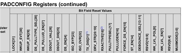
    example, 0x1b0 0x54001 shows pin address having offset 0x1b0 with value 0x54001, wherein the last 3 bits define the muxmode:

  • Dear Sir,

    If I am using a decompiled version of a compiled DTB instead of the original DTS, how can I edit these pinctrl values in the following format?

    pinctrl-single,pins = <0x1d8 0x54001 0x1dc 0x10001>;
    pinctrl-single,pins = <0x1d0 0x64002 0x1d4 0x64002>;

    I understand where to get the offset values such as 0x1d8 and 0x1dc, but from where do values like 0x54001 and 0x64002 come?

    I think these values were not directly written like this in the original DTS file. Am I correct?

    Could you please explain this in more detail?

    Thanks & Regards

    Aparna C Nair

  • Hi Aparna,
    These values fill in PADCONFIG register value per SoC pin as shared in the image of last response.
    You should be able to find macro definitions in driver to fill the same in arch/arm64/boot/dts/ti/k3-pinctrl.h 

  • Dear Sir, 

    From where can I get more information about this pad configuration register? How can I configure it according to our requirements? How should each bit be configured? I checked the datasheet, but I could not find this information. However, I was able to find the offset-related information in the datasheet.

    thanks & Regards

    Aparna C Nair

  • Sir,

    I need one more clarification from your side. Please see the details below:

    root@beagleplay-ti:/boot/dtb/ti# ls


    k3-am625-beagleplay-csi2-ov5640.dtbo


    k3-am625-beagleplay-csi2-tevi-ov5640.dtbo


    k3-am625-beagleplay-lincolntech-lcd185-panel.dtbo

    I can only see .dtbo files. I could not find the corresponding .dts files or k3-pinctrl.h anywhere. I tried to generate a .dtb file from the provided( https://git.ti.com/cgit/ti-linux-kernel/ti-linux-kernel/tree/arch/arm64/boot/dts/ti/k3-am625-beagleplay.dts?h=ti-linux-6.12.y#n405 ) .dts using dtc on my Linux system, but I think it is not possible directly.

    I want to complete this task using the compiler/tools available on the BeaglePlay itself. In which location should I copy the .dts file, and how can I convert it to a .dtb or .dtbo file? Are any additional files required for this process?

    Please guide me on how to customize using the original .dts file that you shared and clarify my doubts.

    Thanks & Regards

    Aparna C Nair

  • Hi Aparna,
    Seems like you are not using the TI SDK.
    Please download and install the Processor SDK from https://www.ti.com/tool/download/PROCESSOR-SDK-LINUX-AM62X  (first link).
    Documentation to use it is given at: https://software-dl.ti.com/processor-sdk-linux/esd/AM62X/latest/exports/docs/devices/AM62X/linux/Overview.html 

    All the files you asked for are provided in the SDK.