This thread has been locked.

If you have a related question, please click the "Ask a related question" button in the top right corner. The newly created question will be automatically linked to this question.

AM62P-Q1: RESETSTATz

Part Number: AM62P-Q1
Other Parts Discussed in Thread: AM62P
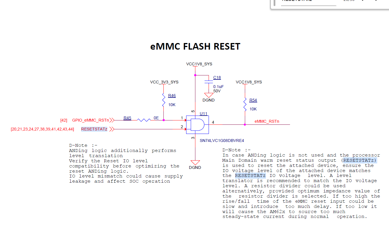
image.png

HI Team,

In the AM62P Evaluation Module (EVM) schematic, I noticed that the RESETSTATz signal is connected to the reset pins through the SN74LVC1G08DBVRE4 AND gate, along with another input signal.

Could you clarify the purpose of using two inputs in the reset logic and whether both signals are required for proper operation?. can I use here single signal for reset devices?.AND gate IC why needed here?. what is the purpose of reseststatz signal?.


  • Hi, 

    Thank you for the query.

    Please refer below an eMMC reset example

    The AND gate produces an eMMC device reset when either RESETSTATZ is asserted low or the GPIO connected to GPIO_eMMC_RSTn is asserted low. The RESETSTATZ signal will be asserted when the AM62x receives a cold reset or a warm reset. This signal is needed to ensure the eMMC device is returned to its initial operating state any time the AM62x device is reset. The GPIO_eMMC_RSTn is provided to allow the eMMC software driver to reset the eMMC device in case it wants to reset the entire eMMC subsystem. 

    Regards,

    Sreenivasa

  • Hi, 

    Additional inputs.

     https://e2e.ti.com/support/processors-group/processors/f/processors-forum/1283208/am623-am623-question-on-sk-am62-design/4866328 

    I have some doubts about the RST circuit design of eMMC;

             U58 is an AND gate, so the output is only high when inputs 1 and 2 are high, otherwise it is low. However, there is also an up pull on the RST side, so the RST side is always high, right?

             Please help explain, thank you

    The GPIO controlled input originates from a AM62x IO that is turned off until the eMMC driver software initializes it to be a software-controlled reset output. The input allows the eMMC software driver to reset the eMMC device without resetting the entire system. The external pull-up on this signal is required to hold the undriven signal high until software initializes the associated GPIO. The device would not be able to boot from eMMC if the signal had an external pull-down attached since the ROM codes doesn't know which GPIO is used to implement a software reset.

    The RESETSTATz input will be driven low when the AM62x device is being reset (power-on reset or warm reset). This input allows the eMMC device to be reset for the first time after the system receives power or if the AM62x device encounters a warm reset event like a watchdog timeout.

    I agree the AND gate output is always driven, so I'm not sure why the hardware team placed a pull-up on that signal. This can be optional.

    Regards,

    Sreenivasa

  • Hi sreenivasa,

        Thank you for your support..

          For my project, cost optimization is important, so I want to avoid using multiple AND gates in the system. Instead, I am considering using FET-based logic or switching methods to reduce component count and cost. Could you suggest a suitable solution for this approach?

  • Hello,

    Keeping U58 provides the most robust, production-ready implementation for a boot-critical reset function. The potential component-level cost reduction from FETs is outweighed by increased risk and validation effort, and it can negatively impact long-term reliability and time-to-market. U58 is a compact, low-cost, high-volume logic device. Replacing it typically adds:

    • Additional discrete components
    • More PCB area and routing complexity
    • More assembly placements
    • When assembly and yield risk are included, the net savings can be minimal or even negative.

    Although a FET-based solution can reduce component cost, we do not recommend replacing U58 with discrete FETs for the eMMC reset function, because it introduces higher technical risk to a boot-critical signal and can increase overall project cost through validation and field reliability impacts. U58 guarantees logic operation across temperature, supply tolerance, and manufacturing variation. Discrete FET implementations depend strongly on parameters such as Vgs(th) spread, leakage, and pull-up strength. Across production lots and temperature extremes, this can change switching behavior and noise margins, making performance less predictable than an IC logic gate.

    Best Regards,

    Borislav Lazarkov

  • Hi, 

    For my project, cost optimization is important, so I want to avoid using multiple AND gates in the system. Instead, I am considering using FET-based logic or switching methods to reduce component count and cost. Could you suggest a suitable solution for this approach?

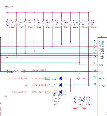
    You could use a diode ANDing logic as below

    https://docs.beagleboard.org/boards/beagleplay/03-design.html

    eMMC/SD

    I am not sure how you will implement using the FET switch.

    In case you do not want to or expect to perform local memory reset, you could only use RESETSTATz

    D-Note:
    In case ANDing logic is not used and the processor Main
    domain warm reset status output (RESETSTATz) is used
    to reset the attached device, ensure the IO voltage level of
    the attached device matches the RESETSTATz IO voltage
    level. A level translator is recommended to match the IO
    voltage level. A resistor divider can be used alternatively,
    provided optimum impedance value of the resistor divider is
    selected. In case the value is too high, the rise/fall time of
    the eMMC reset input can be slow and introduce too much
    delay. In case the value is too low, it will cause the AM62x to
    source too much steady-state current during normal
    operation.

    This reduces design flexibility.

    Regards,

    Sreenivasa

  • Hi,

    Thank you for your support..

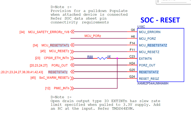
           I can see signals like MCU_RESETSTATZ and PORz_OUT here. I would like to understand which sections are essential for the reset architecture and why separate reset signals are being used in this design. Could you please explain the purpose and necessity of these independent resets?.( And mainly PoRz_Out, MCU_RESETSTATZ.)


  • Hi,

    Thank you.

    I would like to understand which sections are essential for the reset architecture and why separate reset signals are being used in this design.

    Help me understand which design you are referring to - the SK ?

    regards,

    Sreenivasa

  • HI,

    Why PORz_OUT reset specifically going SD card and RGMII only.

  • Hi Please refer below E2E

     https://e2e.ti.com/support/processors-group/processors/f/processors-forum/1274773/am62p5-q1-resetstat-and-porz_out-for-sd-card-power-enable-qa-44 

    FYI, we have customer optimizing the logic to include RESETSTATz and GPIO

    Regards,

    Sreenivasa

  • Hi 

    The observation has been that the RESETSTATz output will satisfy the power-on and warm reset functions for the SD Card.

    So, using a 2-input gate is an allowed approach.

    Regards,

    Sreenivasa 

  • Hi,

    I understand your point, but why is PORz_OUT specifically required for the RGMII and SD-card reset control?.Couldn’t the same reset function be handled only by a GPIO from the processor?

  • Hi,

    Thank you. 

    I understand your point, but why is PORz_OUT specifically required for the RGMII and SD-card reset control?.Couldn’t the same reset function be handled only by a GPIO from the processor?

    SD card

    In case you do not want to use the SD card for boot you can use the SOC IO only. SOC IO buffers are off during reset and after reset until the host configures the IO.

    You can add a pulldown to hold the power switch in off condition, and the SOC can make it high.

    In case boot from SD card is required you can use 3 input ANDing logic with RESETSTAtz and PORz_OUT.

    We realized that using the RESETSTATz along can be good enough to boot.

    EPHY

    In the EPHY case, it is for allowing the EPHY to read the pin straps during power-up

    As You can see RESETSTATz is DNI.

    In case you want to use SOC IO, the software needs to ensure the SPHY interface signals are initialized after the EPHY reset is released.

    Summary is 

    SD card ANDing logic can be optimized to 2 inputs. AND gate

    EPHY ANDing logic also can be optimized to 2 inputs AND gate

    Regards,

    Sreenivasa