


Part Number: TDA4VEN-Q1
hi teams,
I'm working on the SDK mcu_plus_sdk_j722s_11_00_00_12. I tried to change the WUKP I2C0 speed from 400kHz to 1MHz (HS mode). However, when I measured the waveform, I found something unexpected.
According to the datasheet (Section 12.1.2.2.2.4.2, Figure 12-12), the first phase of HS mode transmission – the controller code – should be sent at F/S mode speed (400kHz). Then, after a repeated start (Sr), the target address and data are sent at HS mode speed (1MHz).
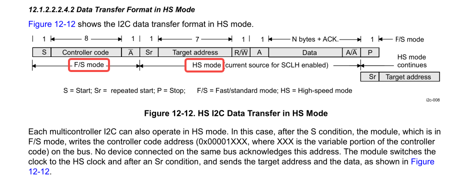
But in my measurement, the first phase runs at about 5MHz, while the second phase is correct at 1MHz. I used a logic analyzer to capture the waveform and decode it – the first phase is much faster than expected.


I checked the I2C driver code. When the speed is set to 1MHz, the configuration registers for F/S mode clock are set to 0. This seems to cause the abnormal 5MHz on the first phase. code in function I2CmasterInitExpClk():
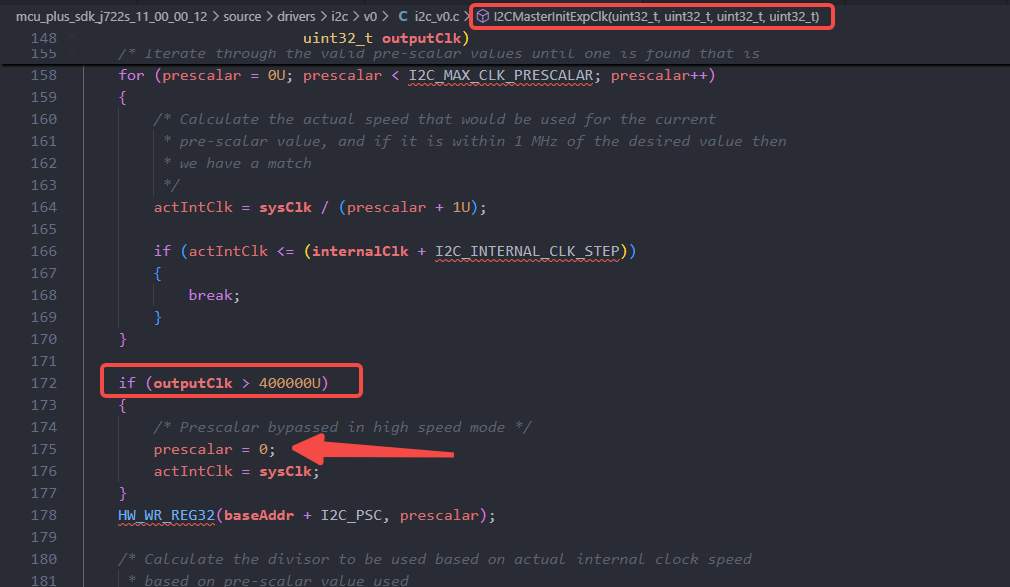
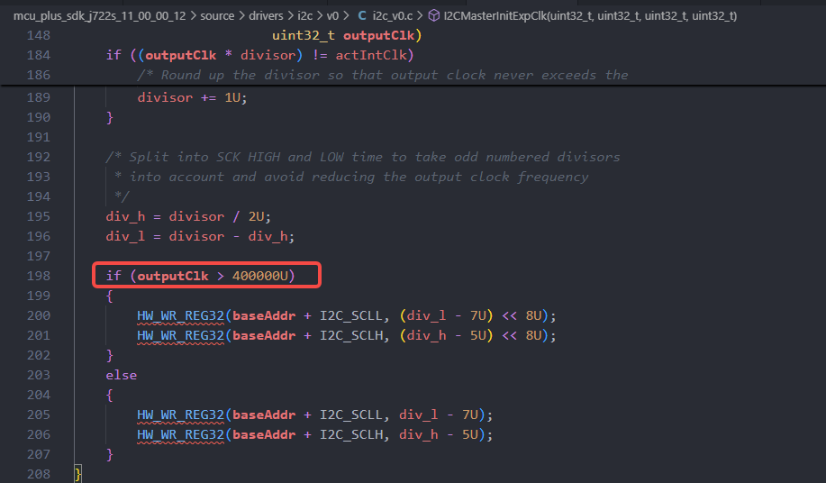
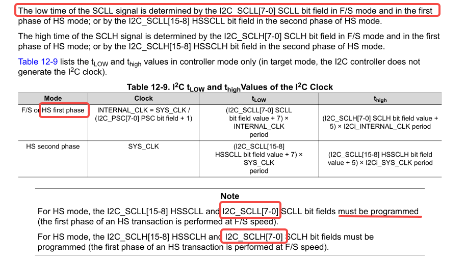
The datasheet also says that the low and high times of SCL during F/S mode and the first phase of HS mode are determined by the lower 8 bits of the SCLL and SCLH registers (I2C_SCLL[7:0] and I2C_SCLH[7:0]). The code doesn't seem to set these correctly.
my questions:
-
Is this a bug in the I2C driver?
- Does this issue affect normal I2C communication? (For example, will devices still work properly?)
Additional observation: Even without modifying the code, the communication do not report any errors, works well. However, looking at the waveform, the START bit itself does not meet the I2C standard.
