This thread has been locked.

If you have a related question, please click the "Ask a related question" button in the top right corner. The newly created question will be automatically linked to this question.

AM2612: Comparators Numbering in AM2612

Part Number: AM2612

Hi, 


we are tring to implement overcurrent detection on a current measruement of the ADC and having issues with it. I notices the CMPSS numbering is a littlebit confusing


Some comparators are connected to multiple ADC inputs. Is this really the case or is there a annotation Issue in this table?


cheers!
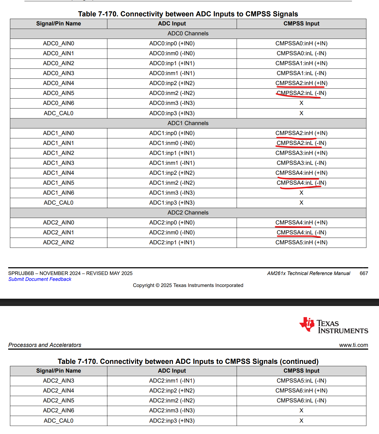
 

image.png

  • Hi Jakob,

    This is the actual hardware design, not a documentation error. Multiple ADC inputs genuinely share physical pins with the same CMPSS comparators. Each ADC module has three sets of differential pins shared with three CMPSSA comparators [1][2].

    The architecture works like this:

    ADC Pins
    CMPSS Connection
    ADC0_AIN0 / ADC0_AIN1
    CMPSSA0 (inH / inL)
    ADC0_AIN2 / ADC0_AIN3
    CMPSSA1 (inH / inL)
    ADC0_AIN4 / ADC0_AIN5
    CMPSSA2 (inH / inL)
    ADC1_AIN0 / ADC1_AIN1
    CMPSSA2 (inH / inL)
    ADC1_AIN2 / ADC1_AIN3
    CMPSSA3 (inH / inL)
    ADC1_AIN4 / ADC1_AIN5
    CMPSSA4 (inH / inL)
    ADC2_AIN0 / ADC2_AIN1
    CMPSSA4 (inH / inL)
    ADC2_AIN2 / ADC2_AIN3
    CMPSSA5 (inH / inL)
    ADC2_AIN4 / ADC2_AIN5
    CMPSSA6 (inH / inL)

    This shared-pin architecture is intentional for power applications — it allows the same analog signal to be simultaneously:

    • Sampled by the ADC for measurement/control
    • Monitored by the CMPSS for fast hardware-based trip detection (overcurrent, overvoltage)

    This eliminates the need for external signal duplication [5].

    For Your Overcurrent Detection

    To configure correctly, identify which specific ADC input pin carries your current measurement signal, then use the connectivity table (Table 7-163 in the TRM or Table 5-5 in the datasheet) to determine the corresponding CMPSS instance and whether your signal maps to the high (inH) or low (inL) comparator input [1][2].

    Note: ADC pins AIN6 and ADC_CAL0 on each ADC module do not have CMPSS connections [2].


    Citations:

    1. AM261x Technical Reference Manual - ADC-CMPSS Signal Connections (p.609)
    2. AM261x Datasheet - ADC-CMPSS Signal Connections (Table 5-5, p.54)
    3. AM261x Datasheet - CMPSS and ADC Connections (Figure 5-5, p.54)
    4. AM261x Technical Reference Manual - ADC-CMPSS Connectivity Table (p.667)
    5. AM261x Technical Reference Manual - CMPSS Overview (p.662)

    Best Regards,

    Zackary Fleenor

  • Hi Zackary,

    thank you very much for the detailed answer. This helps a lot, but there is still something I do not understand. 

    1. Assuming I connect Signal_A to  ADC0_AIN4 and Signal_B to ADC1_AIN0. Is it true that I can connect only one of them to CMPSSA2 or would it be possible to compare both of them. And if I can compare both of them, would it be to the same threshold?

     2. In the Datasheet it is claimed that there are 9 comparators, but as I understand your answer, there is only 7 dedicated units. Is there a way to achieve 9 separate comparissons ideally with different thresholds/references each?

    best regards, Jakob

  • Hi Jakob,

    Great follow-up questions. Let me address both directly.

    Question 1: Signal_A (ADC0_AIN4) and Signal_B (ADC1_AIN0) on CMPSSA2

    Yes, you can compare both simultaneously — with independent thresholds.

    Here's why: ADC0_AIN4 routes to CMPSSA2:inH (the high comparator input), while ADC1_AIN0 routes to CMPSSA2:inL (the low comparator input) [1][2]. These are two physically separate comparators within the same CMPSS instance, each with its own independent 12-bit DAC reference:

    • Signal_A → CMPSSA2 COMPH → threshold set by DACH
    • Signal_B → CMPSSA2 COMPL → threshold set by DACL

    Each DAC has its own programmable value register (DACHVALA / DACLVALA), so you can set different overcurrent thresholds for each signal [3][4].

    Critical constraint: DACH must always be programmed higher than DACL. Additionally, when one comparator trips, it can temporarily disturb the other DAC's output. You must ensure your signal stays more than the "CMPSS DAC output disturbance" value away from the other comparator's trip point during the "CMPSS DAC disturbance time" (both specified in the datasheet electrical characteristics) [3].

    If you're not using one of the comparators, program its DAC register to maximum to prevent false trips from affecting the active comparator [3].

    Question 2: How to Achieve 9 Separate Comparisons

    The AM261x actually has 9 physical CMPSS instances (CMPSSA0 through CMPSSA8) [5][6]. However, only 7 of them (CMPSSA0–CMPSSA6) are connected to ADC input pins per the connectivity tables [1][2]. CMPSSA7 and CMPSSA8 exist as additional comparator units in the device.

    Furthermore, each CMPSS instance contains two independent comparators (COMPH and COMPL) with separate DAC references [4][7]. So the 7 ADC-connected instances alone give you up to 14 comparator inputs (7 × 2), though subject to the DACH > DACL constraint within each instance.

    To achieve 9 separate comparisons with different thresholds, you can use a combination of:

    • The high (COMPH) and low (COMPL) comparators within shared instances (like your CMPSSA2 example)
    • The additional CMPSSA7 and CMPSSA8 instances for signals not routed through ADC pins

    1. AM261x Datasheet - ADC-CMPSS Signal Connections (Table 5-5)
    2. AM261x Technical Reference Manual - ADC-CMPSS Connectivity Table (Table 7-163, p.609)
    3. AM261x Technical Reference Manual - Reference DAC Notes (p.669)
    4. AM261x Technical Reference Manual - CMPSS and ADC Connections (Figure 7-167, p.667)
    5. AM261x Register Reference - CMPSS Instance Table
    6. AM261x Datasheet - Package Comparison (Table 4-1)
    7. AM261x Technical Reference Manual - CMPSS Introduction (p.663)

    Best Regards,

    Zackary Fleenor