AM62P: LVDS BRINGUP IN AM62P5 EVK (ANDROID SDK)

Part Number: AM62P
Other Parts Discussed in Thread: AB15, , SK-LCD1

We are currently working on LVDS display panel 1P.NVDA-TM2118SA123L-03 bring-up on the AM62P5 EVK using the Android SDK (version 11.00.01).

For this setup, we are using the DTBO overlay k3-am62p5-sk-microtips-mf101hie-panel.dtso. Additionally, we have disabled the HDMI bridge (sii9022) in the base device tree file k3-am62p5-sk.dts.

However, we are facing an issue where the clock configurations appear to be incorrect, and the LVDS panel is not displaying any output in Android.
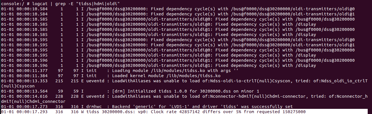
Screenshot from 2026-06-30 17-11-07.png

There is mismatch in the clock for the odi1 transmitter
Screenshot from 2026-06-30 17-12-53.png

  • Hi Vysakh,
    Can you share all your dts and driver (if any) changes here?
    Is this a custom Android build? If so, did you try running with only the default k3-am62p5-sk-microtips-mf101hie-panel.dtbo overlay to check that shows no error on your setup?

    You should not see the oldi-io-ctrl error which is causing the clock rate error in your case. Also, incase you really wish to remove HDMI, I still see an HDMI connector based error. Though harmless, you may have missed removing the HDMI connector node.

  • Hi Divyansh,

    As per your suggestion i disabled the hdmi connector in the dts file.Now no error logs related with hdmi.But we find a syscon error and still we are not obtaining the android display over the LVDS.How can we eliminate this syscon error.Following are the logs:
    /********************************************************************************************************************************************************************/
    console:/ # logcat | grep -E "tidss|oldi|hdmi"
    01-01 00:00:09.638 1 1 I /bus@f0000/dss@30200000: Fixed dependency cycle(s) with /bus@f0000/dss@30200000/oldi-transmitters/oldi@0
    01-01 00:00:09.638 1 1 I /bus@f0000/dss@30200000: Fixed dependency cycle(s) with /bus@f0000/dss@30200000/oldi-transmitters/oldi@1
    01-01 00:00:09.638 1 1 I /bus@f0000/dss@30200000/oldi-transmitters/oldi@0: Fixed dependency cycle(s) with /bus@f0000/dss@30200000
    01-01 00:00:09.638 1 1 I /bus@f0000/dss@30200000/oldi-transmitters/oldi@0: Fixed dependency cycle(s) with /display
    01-01 00:00:09.638 1 1 I /bus@f0000/dss@30200000/oldi-transmitters/oldi@1: Fixed dependency cycle(s) with /bus@f0000/dss@30200000
    01-01 00:00:09.638 1 1 I /bus@f0000/dss@30200000/oldi-transmitters/oldi@1: Fixed dependency cycle(s) with /display
    01-01 00:00:09.649 1 1 I /bus@f0000/dss@30200000: Fixed dependency cycle(s) with /bus@f0000/dss@30200000/oldi-transmitters/oldi@0
    01-01 00:00:09.649 1 1 I /bus@f0000/dss@30200000: Fixed dependency cycle(s) with /bus@f0000/dss@30200000/oldi-transmitters/oldi@1
    01-01 00:00:09.649 1 1 I /bus@f0000/dss@30200000/oldi-transmitters/oldi@0: Fixed dependency cycle(s) with /bus@f0000/dss@30200000
    01-01 00:00:09.649 1 1 I /bus@f0000/dss@30200000/oldi-transmitters/oldi@0: Fixed dependency cycle(s) with /display
    01-01 00:00:09.649 1 1 I /bus@f0000/dss@30200000/oldi-transmitters/oldi@1: Fixed dependency cycle(s) with /bus@f0000/dss@30200000
    01-01 00:00:09.649 1 1 I /bus@f0000/dss@30200000/oldi-transmitters/oldi@1: Fixed dependency cycle(s) with /display
    01-01 00:00:10.427 96 96 I init : Loading module /lib/modules/tidss.ko with args ''
    01-01 00:00:10.433 96 96 I init : Loaded kernel module /lib/modules/tidss.ko
    01-01 00:00:11.788 223 223 E ueventd : LoadWithAliases was unable to load of:Ndss-oldi-io-ctrlT(null)Csyscon, tried: of:Ndss_oldi_io_ctrlT(null)Csyscon
    01-01 00:00:11.942 12 12 I : [drm] Initialized tidss 1.0.0 for 30200000.dss on minor 1
    01-01 00:00:16.341 321 321 I drmhwc : Backend 'generic' for 'LVDS-1' and driver 'tidss' was successfully set
    ^C
    130|console:/ #
    130|console:/ #
    130|console:/ #
    130|console:/ #
    130|console:/ # mount -t debugfs none /sys/kernel/debug
    console:/ # cat /sys/kernel/debug/clk/clk_summary | grep dss
    clock-divider-oldi-dss1 0 0 0 42857142 0 0 50000 Y deviceless no_connection_id
    clk:186:6 1 1 0 320000000 0 0 50000 Y 30200000.dss fck
    clk:186:2 0 0 0 300000000 0 0 50000 Y 30200000.dss vp2
    clock-divider-oldi-dss0 1 1 0 42000000 0 0 50000 Y 30200000.dss vp1
    /*************************************************************************************************************************************************************************/

    We changed the clock frequency to 42Mhz by updating the panel-simple.c driver.Now the previous error clock rate rate differs is removed.
    We are going with base dts file k3-am62p5-sk.dts and for display overlay we are using  k3-am62p5-sk-microtips-mf101hie-panel.dtbo .Only we addded the touch controller node inside the i2c node and and disable the hdmi node.


  • Hi Divyansh

    Forgot to add one more point our display panel supports 1920*720 with clock frequency of 42Mhz.And this is the reason we changed the clock frequency in the  driver.
    We are trying bringup this  display in ANDROID SDK for AM62P5  for the version 11.00.01
    Attaching the log for modetest

    modetest
    trying to open device '/dev/dri/card1'... done
    opened device `TI Keystone DSS` on driver `tidss` (version 1.0.0 at 0)
    Encoders:
    id crtc type possible crtcs possible clones
    40 39 none 0x00000001 0x00000001

    Connectors:
    id encoder status name size (mm) modes encoders
    41 40 connected LVDS-1 217x136 1 40
    modes:
    index name refresh (Hz) hdisp hss hse htot vdisp vss vse vtot
    #0 1920x720 27.99 1920 1952 2004 2028 720 730 735 740 42000 flags: ; type: preferred, driver
    props:
    1 EDID:
    flags: immutable blob
    blobs:

    value:
    2 DPMS:
    flags: enum
    enums: On=0 Standby=1 Suspend=2 Off=3
    value: 0
    5 link-status:
    flags: enum
    enums: Good=0 Bad=1
    value: 0
    6 non-desktop:
    flags: immutable range
    values: 0 1
    value: 0
    4 TILE:
    flags: immutable blob
    blobs:

    value:

    CRTCs:
    id fb pos size
    39 54 (0,0) (1920x720)
    #0 1920x720 27.99 1920 1952 2004 2028 720 730 735 740 42000 flags: ; type: preferred, driver
    props:
    24 VRR_ENABLED:
    flags: range
    values: 0 1
    value: 0
    27 CTM:
    flags: blob
    blobs:

    value:
    00000000010000000000000000000000
    00000000000000000000000000000000
    00000000010000000000000000000000
    00000000000000000000000000000000
    0000000001000000
    28 GAMMA_LUT:
    flags: blob
    blobs:

    value:
    29 GAMMA_LUT_SIZE:
    flags: immutable range
    values: 0 4294967295
    value: 256

    Planes:
    id crtc fb CRTC x,y x,y gamma size possible crtcs
    32 39 54 0,0 0,0 0 0x00000001
    formats: AR12 AB12 RA12 RG16 BG16 AR15 AB15 AR24 AB24 RA24 BA24 RG24 BG24 AR30 AB30 XR12 XB12 RX12 XR15 XB15 XR24 XB24 RX24 BX24 XR30 XB30 YUYV UYVY NV12
    props:
    8 type:
    flags: immutable enum
    enums: Overlay=0 Primary=1 Cursor=2
    value: 1
    30 IN_FORMATS:
    flags: immutable blob
    blobs:

    value:
    01000000000000001d00000018000000
    01000000900000004152313241423132
    52413132524731364247313641523135
    41423135415232344142323452413234
    42413234524732344247323441523330
    41423330585231325842313252583132
    58523135584231355852323458423234
    52583234425832345852333058423330
    59555956555956594e56313200000000
    ffffff1f000000000000000000000000
    0000000000000000
    in_formats blob decoded:
    AR12: LINEAR(0x0)
    AB12: LINEAR(0x0)
    RA12: LINEAR(0x0)
    RG16: LINEAR(0x0)
    BG16: LINEAR(0x0)
    AR15: LINEAR(0x0)
    AB15: LINEAR(0x0)
    AR24: LINEAR(0x0)
    AB24: LINEAR(0x0)
    RA24: LINEAR(0x0)
    BA24: LINEAR(0x0)
    RG24: LINEAR(0x0)
    BG24: LINEAR(0x0)
    AR30: LINEAR(0x0)
    AB30: LINEAR(0x0)
    XR12: LINEAR(0x0)
    XB12: LINEAR(0x0)
    RX12: LINEAR(0x0)
    XR15: LINEAR(0x0)
    XB15: LINEAR(0x0)
    XR24: LINEAR(0x0)
    XB24: LINEAR(0x0)
    RX24: LINEAR(0x0)
    BX24: LINEAR(0x0)
    XR30: LINEAR(0x0)
    XB30: LINEAR(0x0)
    YUYV: LINEAR(0x0)
    UYVY: LINEAR(0x0)
    NV12: LINEAR(0x0)
    34 zpos:
    flags: range
    values: 0 1
    value: 0
    35 COLOR_ENCODING:
    flags: enum
    enums: ITU-R BT.601 YCbCr=0 ITU-R BT.709 YCbCr=1
    value: 1
    36 COLOR_RANGE:
    flags: enum
    enums: YCbCr limited range=0 YCbCr full range=1
    value: 1
    37 alpha:
    flags: range
    values: 0 65535
    value: 65535
    38 pixel blend mode:
    flags: enum
    enums: Pre-multiplied=0 Coverage=1
    value: 0
    42 39 62 0,0 0,0 0 0x00000001
    formats: AR12 AB12 RA12 RG16 BG16 AR15 AB15 AR24 AB24 RA24 BA24 RG24 BG24 AR30 AB30 XR12 XB12 RX12 XR15 XB15 XR24 XB24 RX24 BX24 XR30 XB30 YUYV UYVY NV12
    props:
    8 type:
    flags: immutable enum
    enums: Overlay=0 Primary=1 Cursor=2
    value: 0
    30 IN_FORMATS:
    flags: immutable blob
    blobs:

    value:
    01000000000000001d00000018000000
    01000000900000004152313241423132
    52413132524731364247313641523135
    41423135415232344142323452413234
    42413234524732344247323441523330
    41423330585231325842313252583132
    58523135584231355852323458423234
    52583234425832345852333058423330
    59555956555956594e56313200000000
    ffffff1f000000000000000000000000
    0000000000000000
    in_formats blob decoded:
    AR12: LINEAR(0x0)
    AB12: LINEAR(0x0)
    RA12: LINEAR(0x0)
    RG16: LINEAR(0x0)
    BG16: LINEAR(0x0)
    AR15: LINEAR(0x0)
    AB15: LINEAR(0x0)
    AR24: LINEAR(0x0)
    AB24: LINEAR(0x0)
    RA24: LINEAR(0x0)
    BA24: LINEAR(0x0)
    RG24: LINEAR(0x0)
    BG24: LINEAR(0x0)
    AR30: LINEAR(0x0)
    AB30: LINEAR(0x0)
    XR12: LINEAR(0x0)
    XB12: LINEAR(0x0)
    RX12: LINEAR(0x0)
    XR15: LINEAR(0x0)
    XB15: LINEAR(0x0)
    XR24: LINEAR(0x0)
    XB24: LINEAR(0x0)
    RX24: LINEAR(0x0)
    BX24: LINEAR(0x0)
    XR30: LINEAR(0x0)
    XB30: LINEAR(0x0)
    YUYV: LINEAR(0x0)
    UYVY: LINEAR(0x0)
    NV12: LINEAR(0x0)
    44 zpos:
    flags: range
    values: 0 1
    value: 1
    45 COLOR_ENCODING:
    flags: enum
    enums: ITU-R BT.601 YCbCr=0 ITU-R BT.709 YCbCr=1
    value: 1
    46 COLOR_RANGE:
    flags: enum
    enums: YCbCr limited range=0 YCbCr full range=1
    value: 1
    47 alpha:
    flags: range
    values: 0 65535
    value: 65535
    48 pixel blend mode:
    flags: enum
    enums: Pre-multiplied=0 Coverage=1
    value: 0

    Frame buffers:
    id size pitch

  • Hi Vysakh,

    Now the previous error clock rate rate differs is removed.

    Does kmstest show something valid on the screen? Is this issue now resolved?
    If not, please share all the driver changes you have.

    P.S Please use the code blocks in future to share any code/logs.

  • Hi Divyansh,

    The issue is not resolved.
    This is an android image and doesnt support any packages like kmstest.Could you please provide some debugging steps in android where i can check the issue.We didnt bring much changes in the driver.For the bringup we are using panel-simple.c driver.
    Attaching the driver,dts and overlay file.We are trying to bring up this in Android Platform.Could you please go through the files and guide us what we are missing in this bringup process

    7026.panel-simple.c

    // SPDX-License-Identifier: GPL-2.0-only OR MIT
    /*
     * Device Tree file for the AM62P5-SK
     * Copyright (C) 2023-2024 Texas Instruments Incorporated - https://www.ti.com/
     *
     * Schematics: https://www.ti.com/lit/zip/sprr487
     */
    
    /dts-v1/;
    
    #include <dt-bindings/leds/common.h>
    #include <dt-bindings/gpio/gpio.h>
    #include <dt-bindings/net/ti-dp83867.h>
    #include "k3-am62p5.dtsi"
    
    / {
    	compatible = "ti,am62p5-sk", "ti,am62p5";
    	model = "Texas Instruments AM62P5 SK";
    
    	aliases {
    		serial0 = &wkup_uart0;
    		serial1 = &mcu_uart0;
    		serial2 = &main_uart0;
    		serial3 = &main_uart1;
    		mmc0 = &sdhci0;
    		mmc1 = &sdhci1;
    		mmc2 = &sdhci2;
    		spi0 = &ospi0;
    		ethernet0 = &cpsw_port1;
    		ethernet1 = &cpsw_port2;
    		usb0 = &usb0;
    		usb1 = &usb1;
    	};
    
    	chosen {
    		#address-cells = <2>;
    		#size-cells = <2>;
    		ranges;
    
    		stdout-path = &main_uart0;
    
    		framebuffer0: framebuffer@0 {
    			compatible = "simple-framebuffer";
    			power-domains = <&k3_pds 186 TI_SCI_PD_EXCLUSIVE>;
    			clocks = <&k3_clks 186 6>,
    				 <&dss0_vp1_clk>,
    				 <&k3_clks 186 2>;
    			display = <&dss0>;
    			status = "disabled";
    		};
    	};
    
    	memory@80000000 {
    		/* 8G RAM */
    		reg = <0x00000000 0x80000000 0x00000000 0x80000000>,
    		      <0x00000008 0x80000000 0x00000001 0x80000000>;
    		device_type = "memory";
    		bootph-pre-ram;
    	};
    
    	reserved_memory: reserved-memory {
    		#address-cells = <2>;
    		#size-cells = <2>;
    		ranges;
    
    		linux,cma {
    			compatible = "shared-dma-pool";
    			reusable;
    			size = <0x00 0x24000000>;
    			linux,cma-default;
    		};
    
    		rtos_ipc_memory_region: rtos-ipc-memory@9b500000 {
    			compatible = "shared-dma-pool";
    			reg = <0x00 0x9b500000 0x00 0x00300000>;
    			no-map;
    		};
    
    		mcu_r5fss0_core0_dma_memory_region: mcu-r5fss-dma-memory-region@9b800000 {
    			compatible = "shared-dma-pool";
    			reg = <0x00 0x9b800000 0x00 0x100000>;
    			no-map;
    		};
    
    		mcu_r5fss0_core0_memory_region: mcu-r5fss-memory-region@9b900000 {
    			compatible = "shared-dma-pool";
    			reg = <0x00 0x9b900000 0x00 0xf00000>;
    			no-map;
    		};
    
    		wkup_r5fss0_core0_dma_memory_region: r5f-dma-memory@9c800000 {
    			compatible = "shared-dma-pool";
    			reg = <0x00 0x9c800000 0x00 0x100000>;
    			no-map;
    		};
    
    		wkup_r5fss0_core0_memory_region: r5f-memory@9c900000 {
    			compatible = "shared-dma-pool";
    			reg = <0x00 0x9c900000 0x00 0x1e00000>;
    			no-map;
    		};
    
    		secure_tfa_ddr: tfa@9e780000 {
    			reg = <0x00 0x9e780000 0x00 0x80000>;
    			no-map;
    		};
    
    		secure_ddr: optee@9e800000 {
    			reg = <0x00 0x9e800000 0x00 0x01800000>; /* for OP-TEE */
    			no-map;
    		};
    
    		carveout_video: video {
    			compatible = "dma-heap-carveout";
    			reg = <0x00 0xa0000000 0x00 0x29000000>;
    			no-map;
    		};
    	};
    
    	vmain_pd: regulator-0 {
    		/* TPS65988 PD CONTROLLER OUTPUT */
    		compatible = "regulator-fixed";
    		regulator-name = "vmain_pd";
    		regulator-min-microvolt = <5000000>;
    		regulator-max-microvolt = <5000000>;
    		regulator-always-on;
    		regulator-boot-on;
    		bootph-all;
    	};
    
    	vcc_5v0: regulator-1 {
    		/* Output of TPS630702RNMR */
    		compatible = "regulator-fixed";
    		regulator-name = "vcc_5v0";
    		regulator-min-microvolt = <5000000>;
    		regulator-max-microvolt = <5000000>;
    		vin-supply = <&vmain_pd>;
    		regulator-always-on;
    		regulator-boot-on;
    		bootph-all;
    	};
    
    	vdd_mmc1: regulator-2 {
    		/* TPS22918DBVR */
    		compatible = "regulator-fixed";
    		regulator-name = "vdd_mmc1";
    		regulator-min-microvolt = <3300000>;
    		regulator-max-microvolt = <3300000>;
    		regulator-boot-on;
    		enable-active-high;
    		gpio = <&exp1 3 GPIO_ACTIVE_HIGH>;
    		bootph-all;
    	};
    
    	vddshv_sdio: regulator-3 {
    		compatible = "regulator-gpio";
    		regulator-name = "vddshv_sdio";
    		pinctrl-names = "default";
    		pinctrl-0 = <&vddshv_sdio_pins_default>;
    		regulator-min-microvolt = <1800000>;
    		regulator-max-microvolt = <3300000>;
    		regulator-boot-on;
    		gpios = <&main_gpio0 31 GPIO_ACTIVE_HIGH>;
    		states = <1800000 0x0>,
    			 <3300000 0x1>;
    		bootph-all;
    	};
    
    	leds {
    		compatible = "gpio-leds";
    		pinctrl-names = "default";
    		pinctrl-0 = <&usr_led_pins_default>;
    
    		led-0 {
    			label = "am62-sk:green:heartbeat";
    			gpios = <&main_gpio1 49 GPIO_ACTIVE_HIGH>;
    			linux,default-trigger = "heartbeat";
    			function = LED_FUNCTION_HEARTBEAT;
    			default-state = "off";
    		};
    	};
    
    	opp-table {
    		/* Requires VDD_CORE at 0v85 */
    		opp-1400000000 {
    			opp-hz = /bits/ 64 <1400000000>;
    			opp-supported-hw = <0x01 0x0004>;
    			clock-latency-ns = <6000000>;
    		};
    	};
    
    	tlv320_mclk: clk-0 {
    		#clock-cells = <0>;
    		compatible = "fixed-clock";
    		clock-frequency = <12288000>;
    	};
    
    	codec_audio: sound {
    		compatible = "simple-audio-card";
    		simple-audio-card,name = "AM62x-SKEVM";
    		simple-audio-card,widgets =
    			"Headphone",	"Headphone Jack",
    			"Line",		"Line In",
    			"Microphone",	"Microphone Jack";
    		simple-audio-card,routing =
    			"Headphone Jack",	"HPLOUT",
    			"Headphone Jack",	"HPROUT",
    			"LINE1L",		"Line In",
    			"LINE1R",		"Line In",
    			"MIC3R",		"Microphone Jack",
    			"Microphone Jack",	"Mic Bias";
    		simple-audio-card,format = "dsp_b";
    		simple-audio-card,bitclock-master = <&sound_master>;
    		simple-audio-card,frame-master = <&sound_master>;
    		simple-audio-card,bitclock-inversion;
    
    		simple-audio-card,cpu {
    			sound-dai = <&mcasp1>;
    		};
    
    		sound_master: simple-audio-card,codec {
    			sound-dai = <&tlv320aic3106>;
    			clocks = <&tlv320_mclk>;
    		};
    	};
    
    	hdmi0: connector-hdmi {
    		compatible = "hdmi-connector";
    		label = "hdmi";
    		type = "a";
    		status = "disabled";
    		port {
    			hdmi_connector_in: endpoint {
    				remote-endpoint = <&sii9022_out>;
    			};
    		};
    	};
    };
    
    &main_gpio0 {
    	bootph-all;
    };
    
    &main_gpio1 {
    	bootph-all;
    };
    
    &main_pmx0 {
    	bootph-all;
    
    	main_i2c0_pins_default: main-i2c0-default-pins {
    		pinctrl-single,pins = <
    			AM62PX_IOPAD(0x01e0, PIN_INPUT_PULLUP, 0) /* (B25) I2C0_SCL */
    			AM62PX_IOPAD(0x01e4, PIN_INPUT_PULLUP, 0) /* (A24) I2C0_SDA */
    		>;
    	};
    
    	main_i2c1_pins_default: main-i2c1-default-pins {
    		pinctrl-single,pins = <
    			AM62PX_IOPAD(0x01e8, PIN_INPUT_PULLUP, 0) /* (C24) I2C1_SCL */
    			AM62PX_IOPAD(0x01ec, PIN_INPUT_PULLUP, 0) /* (B24) I2C1_SDA */
    		>;
    		bootph-all;
    	};
    
    	main_i2c2_pins_default: main-i2c2-default-pins {
    		pinctrl-single,pins = <
    			AM62PX_IOPAD(0x00b0, PIN_INPUT_PULLUP, 1) /* (T22) GPMC0_CSn2.I2C2_SCL */
    			AM62PX_IOPAD(0x00b4, PIN_INPUT_PULLUP, 1) /* (U25) GPMC0_CSn3.I2C2_SDA */
    		>;
    	};
    
    	main_gpio1_ioexp_intr_pins_default: main-gpio1-ioexp-intr-default-pins {
    		pinctrl-single,pins = <
    			AM62PX_IOPAD(0x01d4, PIN_INPUT, 7) /* (C22) UART0_RTSn.GPIO1_23 */
    		>;
    	};
    
    	main_mcasp1_pins_default: main-mcasp1-default-pins {
    		pinctrl-single,pins = <
    			AM62PX_IOPAD(0x0090, PIN_INPUT, 2) /* (U24) GPMC0_BE0n_CLE.MCASP1_ACLKX */
    			AM62PX_IOPAD(0x0098, PIN_INPUT, 2) /* (AA24) GPMC0_WAIT0.MCASP1_AFSX */
    			AM62PX_IOPAD(0x008c, PIN_OUTPUT, 2) /* (T25) GPMC0_WEn.MCASP1_AXR0 */
    			AM62PX_IOPAD(0x0084, PIN_INPUT, 2) /* (R25) GPMC0_ADVn_ALE.MCASP1_AXR2 */
    		>;
    	};
    
    	main_mdio1_pins_default: main-mdio1-default-pins {
    		pinctrl-single,pins = <
    			AM62PX_IOPAD(0x0160, PIN_OUTPUT, 0) /* (F17) MDIO0_MDC */
    			AM62PX_IOPAD(0x015c, PIN_INPUT, 0) /* (F16) MDIO0_MDIO */
    		>;
    		bootph-all;
    	};
    
    	main_mmc1_pins_default: main-mmc1-default-pins {
    		pinctrl-single,pins = <
    			AM62PX_IOPAD(0x023c, PIN_INPUT, 0) /* (H20) MMC1_CMD */
    			AM62PX_IOPAD(0x0234, PIN_OUTPUT, 0) /* (J24) MMC1_CLK */
    			AM62PX_IOPAD(0x0230, PIN_INPUT, 0) /* (H21) MMC1_DAT0 */
    			AM62PX_IOPAD(0x022c, PIN_INPUT, 0) /* (H23) MMC1_DAT1 */
    			AM62PX_IOPAD(0x0228, PIN_INPUT, 0) /* (H22) MMC1_DAT2 */
    			AM62PX_IOPAD(0x0224, PIN_INPUT, 0) /* (H25) MMC1_DAT3 */
    			AM62PX_IOPAD(0x0240, PIN_INPUT, 0) /* (D23) MMC1_SDCD */
    		>;
    		bootph-all;
    	};
    
    	main_mmc2_pins_default: main-mmc2-default-pins {
    		pinctrl-single,pins = <
    			AM62PX_IOPAD(0x0120, PIN_INPUT, 0) /* (K24) MMC2_CMD */
    			AM62PX_IOPAD(0x0118, PIN_OUTPUT, 0) /* (K21) MMC2_CLK */
    			AM62PX_IOPAD(0x011C, PIN_INPUT, 0) /* () MMC2_CLKLB */
    			AM62PX_IOPAD(0x0114, PIN_INPUT, 0) /* (K23) MMC2_DAT0 */
    			AM62PX_IOPAD(0x0110, PIN_INPUT_PULLUP, 0) /* (K22) MMC2_DAT1 */
    			AM62PX_IOPAD(0x010c, PIN_INPUT_PULLUP, 0) /* (L20) MMC2_DAT2 */
    			AM62PX_IOPAD(0x0108, PIN_INPUT_PULLUP, 0) /* (L21) MMC2_DAT3 */
    		>;
    		bootph-all;
    	};
    
    	main_rgmii1_pins_default: main-rgmii1-default-pins {
    		pinctrl-single,pins = <
    			AM62PX_IOPAD(0x014c, PIN_INPUT, 0) /* (B15) RGMII1_RD0 */
    			AM62PX_IOPAD(0x0150, PIN_INPUT, 0) /* (B16) RGMII1_RD1 */
    			AM62PX_IOPAD(0x0154, PIN_INPUT, 0) /* (A14) RGMII1_RD2 */
    			AM62PX_IOPAD(0x0158, PIN_INPUT, 0) /* (B14) RGMII1_RD3 */
    			AM62PX_IOPAD(0x0148, PIN_INPUT, 0) /* (A16) RGMII1_RXC */
    			AM62PX_IOPAD(0x0144, PIN_INPUT, 0) /* (A15) RGMII1_RX_CTL */
    			AM62PX_IOPAD(0x0134, PIN_INPUT, 0) /* (A18) RGMII1_TD0 */
    			AM62PX_IOPAD(0x0138, PIN_INPUT, 0) /* (C17) RGMII1_TD1 */
    			AM62PX_IOPAD(0x013c, PIN_INPUT, 0) /* (A17) RGMII1_TD2 */
    			AM62PX_IOPAD(0x0140, PIN_INPUT, 0) /* (C16) RGMII1_TD3 */
    			AM62PX_IOPAD(0x0130, PIN_INPUT, 0) /* (B17) RGMII1_TXC */
    			AM62PX_IOPAD(0x012c, PIN_INPUT, 0) /* (B18) RGMII1_TX_CTL */
    		>;
    		bootph-all;
    	};
    
    	main_rgmii2_pins_default: main-rgmii2-default-pins {
    		pinctrl-single,pins = <
    			AM62PX_IOPAD(0x0184, PIN_INPUT, 0) /* (E19) RGMII2_RD0 */
    			AM62PX_IOPAD(0x0188, PIN_INPUT, 0) /* (E16) RGMII2_RD1 */
    			AM62PX_IOPAD(0x018c, PIN_INPUT, 0) /* (E17) RGMII2_RD2 */
    			AM62PX_IOPAD(0x0190, PIN_INPUT, 0) /* (C19) RGMII2_RD3 */
    			AM62PX_IOPAD(0x0180, PIN_INPUT, 0) /* (D19) RGMII2_RXC */
    			AM62PX_IOPAD(0x017c, PIN_INPUT, 0) /* (F19) RGMII2_RX_CTL */
    			AM62PX_IOPAD(0x016c, PIN_INPUT, 0) /* (B19) RGMII2_TD0 */
    			AM62PX_IOPAD(0x0170, PIN_INPUT, 0) /* (A21) RGMII2_TD1 */
    			AM62PX_IOPAD(0x0174, PIN_INPUT, 0) /* (D17) RGMII2_TD2 */
    			AM62PX_IOPAD(0x0178, PIN_INPUT, 0) /* (A19) RGMII2_TD3 */
    			AM62PX_IOPAD(0x0168, PIN_INPUT, 0) /* (D16) RGMII2_TXC */
    			AM62PX_IOPAD(0x0164, PIN_INPUT, 0) /* (A20) RGMII2_TX_CTL */
    		>;
    		bootph-all;
    	};
    
    	main_uart0_pins_default: main-uart0-default-pins {
    		pinctrl-single,pins = <
    			AM62PX_IOPAD(0x1c8, PIN_INPUT, 0)	/* (A22) UART0_RXD */
    			AM62PX_IOPAD(0x1cc, PIN_OUTPUT, 0)	/* (B22) UART0_TXD */
    		>;
    		bootph-all;
    	};
    
    	main_uart1_pins_default: main-uart1-default-pins {
    		pinctrl-single,pins = <
    			AM62PX_IOPAD(0x0194, PIN_INPUT, 2) /* (D25) MCASP0_AXR3.UART1_CTSn */
    			AM62PX_IOPAD(0x0198, PIN_OUTPUT, 2) /* (E25) MCASP0_AXR2.UART1_RTSn */
    			AM62PX_IOPAD(0x01ac, PIN_INPUT, 2) /* (G23) MCASP0_AFSR.UART1_RXD */
    			AM62PX_IOPAD(0x01b0, PIN_OUTPUT, 2) /* (G20) MCASP0_ACLKR.UART1_TXD */
    		>;
    		bootph-all;
    	};
    
    	main_usb1_pins_default: main-usb1-default-pins {
    		pinctrl-single,pins = <
    			AM62PX_IOPAD(0x0258, PIN_INPUT | PIN_DS_PULLUD_ENABLE | PIN_DS_PULL_UP, 0) /* (G21) USB1_DRVVBUS */
    		>;
    	};
    
    	main_wlirq_pins_default: main-wlirq-default-pins {
    		pinctrl-single,pins = <
    			AM62PX_IOPAD(0x0128, PIN_INPUT, 7) /* (K25) MMC2_SDWP.GPIO0_72 */
    		>;
    	};
    
    	ospi0_pins_default: ospi0-default-pins {
    		pinctrl-single,pins = <
    			AM62PX_IOPAD(0x0000, PIN_OUTPUT, 0) /* (P23) OSPI0_CLK */
    			AM62PX_IOPAD(0x002c, PIN_OUTPUT, 0) /* (M25) OSPI0_CSn0 */
    			AM62PX_IOPAD(0x000c, PIN_INPUT, 0) /* (L25) OSPI0_D0 */
    			AM62PX_IOPAD(0x0010, PIN_INPUT, 0) /* (N24) OSPI0_D1 */
    			AM62PX_IOPAD(0x0014, PIN_INPUT, 0) /* (N25) OSPI0_D2 */
    			AM62PX_IOPAD(0x0018, PIN_INPUT, 0) /* (M24) OSPI0_D3 */
    			AM62PX_IOPAD(0x001c, PIN_INPUT, 0) /* (N21) OSPI0_D4 */
    			AM62PX_IOPAD(0x0020, PIN_INPUT, 0) /* (N22) OSPI0_D5 */
    			AM62PX_IOPAD(0x0024, PIN_INPUT, 0) /* (P21) OSPI0_D6 */
    			AM62PX_IOPAD(0x0028, PIN_INPUT, 0) /* (N20) OSPI0_D7 */
    			AM62PX_IOPAD(0x0008, PIN_INPUT, 0) /* (P22) OSPI0_DQS */
    		>;
    		bootph-all;
    	};
    
    	usr_led_pins_default: usr-led-default-pins {
    		pinctrl-single,pins = <
    			AM62PX_IOPAD(0x0244, PIN_INPUT, 7) /* (D24) MMC1_SDWP.GPIO1_49 */
    		>;
    	};
    
    	vddshv_sdio_pins_default: vddshvr-sdio-default-pins {
    		pinctrl-single,pins = <
    			AM62PX_IOPAD(0x007c, PIN_INPUT, 7) /* (Y25) GPMC0_CLK.GPIO0_31 */
    		>;
    		bootph-all;
    	};
    
    	wlan_en_pins_default: wlan-en-default-pins {
    		pinctrl-single,pins = <
    			AM62PX_IOPAD(0x0124, PIN_INPUT, 7) /* (J25) MMC2_SDCD.GPIO0_71 */
    		>;
    	};
    
    	main_dpi_pins_default: main-dpi-default-pins {
    		pinctrl-single,pins = <
    			AM62PX_IOPAD(0x0100, PIN_OUTPUT, 0) /* (W20) VOUT0_VSYNC */
    			AM62PX_IOPAD(0x00f8, PIN_OUTPUT, 0) /* (AC20) VOUT0_HSYNC */
    			AM62PX_IOPAD(0x0104, PIN_OUTPUT, 0) /* (Y21) VOUT0_PCLK */
    			AM62PX_IOPAD(0x00fc, PIN_OUTPUT, 0) /* (W21) VOUT0_DE */
    			AM62PX_IOPAD(0x00b8, PIN_OUTPUT, 0) /* (AE24) VOUT0_DATA0 */
    			AM62PX_IOPAD(0x00bc, PIN_OUTPUT, 0) /* (W23) VOUT0_DATA1 */
    			AM62PX_IOPAD(0x00c0, PIN_OUTPUT, 0) /* (AA23) VOUT0_DATA2 */
    			AM62PX_IOPAD(0x00c4, PIN_OUTPUT, 0) /* (Y23) VOUT0_DATA3 */
    			AM62PX_IOPAD(0x00c8, PIN_OUTPUT, 0) /* (AB23) VOUT0_DATA4 */
    			AM62PX_IOPAD(0x00cc, PIN_OUTPUT, 0) /* (AD23) VOUT0_DATA5 */
    			AM62PX_IOPAD(0x00d0, PIN_OUTPUT, 0) /* (AC23) VOUT0_DATA6 */
    			AM62PX_IOPAD(0x00d4, PIN_OUTPUT, 0) /* (AE23) VOUT0_DATA7 */
    			AM62PX_IOPAD(0x00d8, PIN_OUTPUT, 0) /* (AE22) VOUT0_DATA8 */
    			AM62PX_IOPAD(0x00dc, PIN_OUTPUT, 0) /* (AC22) VOUT0_DATA9 */
    			AM62PX_IOPAD(0x00e0, PIN_OUTPUT, 0) /* (W22) VOUT0_DATA10 */
    			AM62PX_IOPAD(0x00e4, PIN_OUTPUT, 0) /* (AE21) VOUT0_DATA11 */
    			AM62PX_IOPAD(0x00e8, PIN_OUTPUT, 0) /* (AD21) VOUT0_DATA12 */
    			AM62PX_IOPAD(0x00ec, PIN_OUTPUT, 0) /* (AC21) VOUT0_DATA13 */
    			AM62PX_IOPAD(0x00f0, PIN_OUTPUT, 0) /* (AA20) VOUT0_DATA14 */
    			AM62PX_IOPAD(0x00f4, PIN_OUTPUT, 0) /* (Y20) VOUT0_DATA15 */
    			AM62PX_IOPAD(0x005c, PIN_OUTPUT, 1) /* (AC25) GPMC0_AD8.VOUT0_DATA16 */
    			AM62PX_IOPAD(0x0060, PIN_OUTPUT, 1) /* (AB25) GPMC0_AD9.VOUT0_DATA17 */
    			AM62PX_IOPAD(0x0064, PIN_OUTPUT, 1) /* (AA25) GPMC0_AD10.VOUT0_DATA18 */
    			AM62PX_IOPAD(0x0068, PIN_OUTPUT, 1) /* (W24) GPMC0_AD11.VOUT0_DATA19 */
    			AM62PX_IOPAD(0x006c, PIN_OUTPUT, 1) /* (Y24) GPMC0_AD12.VOUT0_DATA20 */
    			AM62PX_IOPAD(0x0070, PIN_OUTPUT, 1) /* (AD25) GPMC0_AD13.VOUT0_DATA21 */
    			AM62PX_IOPAD(0x0074, PIN_OUTPUT, 1) /* (AB24) GPMC0_AD14.VOUT0_DATA22 */
    			AM62PX_IOPAD(0x0078, PIN_OUTPUT, 1) /* (AC24) GPMC0_AD15.VOUT0_DATA23 */
    			AM62PX_IOPAD(0x009c, PIN_OUTPUT, 1) /* (AD24) GPMC0_WAIT1.VOUT0_EXTPCLKIN */
    		>;
    	};
    
    	main_epwm0_pins_default: main_epwm0-default-pins {
    		pinctrl-single,pins = <
    			AM62PX_IOPAD(0x01b4, PIN_OUTPUT, 2) /* (D20) SPI0_CS0.EHRPWM0_A */
    			AM62PX_IOPAD(0x01b8, PIN_OUTPUT, 2) /* (E20) SPI0_CS1.EHRPWM0_B */
    		>;
    	};
    
    	main_epwm1_pins_default: main_epwm1-default-pins {
    		pinctrl-single,pins = <
    			AM62PX_IOPAD(0x01bc, PIN_OUTPUT, 2) /* (B21) SPI0_CLK.EHRPWM1_A */
    			AM62PX_IOPAD(0x01c0, PIN_OUTPUT, 2) /* (B20) SPI0_D0.EHRPWM1_B */
    		>;
    	};
    
    	main_ecap1_pins_default: main_ecap1-default-pins {
    		pinctrl-single,pins = <
    			AM62PX_IOPAD(0x019c, PIN_OUTPUT, 2) /* (E24) MCASP0_AXR1.ECAP1_IN_APWM_OUT */
    		>;
    	};
    
    	main_ecap2_pins_default: main-ecap2-default-pins {
    		pinctrl-single,pins = <
    			AM62PX_IOPAD(0x01a4, PIN_OUTPUT, 2) /* (F24) MCASP0_ACLKX.ECAP2_IN_APWM_OUT */
    		>;
    	};
    };
    
    &main_i2c0 {
    	status = "okay";
    	pinctrl-names = "default";
    	pinctrl-0 = <&main_i2c0_pins_default>;
    	clock-frequency = <400000>;
    
    	typec_pd0: usb-power-controller@3f {
    		compatible = "ti,tps6598x";
    		reg = <0x3f>;
    
    		connector {
    			compatible = "usb-c-connector";
    			label = "USB-C";
    			self-powered;
    			data-role = "dual";
    			power-role = "sink";
    			port {
    				usb_con_hs: endpoint {
    				remote-endpoint = <&usb0_hs_ep>;
    				};
    			};
    		};
    	};
    touchscreen@4a {
    			   compatible = "atmel,maxtouch";
    			   reg = <0x4a>;
    
    			   interrupt-parent = <&main_gpio0>;
    			   interrupts = <16 IRQ_TYPE_EDGE_FALLING>;
    
    			   status = "okay";
    		   };
    
    };
    
    &main_i2c1 {
    	status = "okay";
    	pinctrl-names = "default";
    	pinctrl-0 = <&main_i2c1_pins_default>;
    	clock-frequency = <100000>;
    	bootph-all;
    
    	tlv320aic3106: audio-codec@1b {
    		#sound-dai-cells = <0>;
    		compatible = "ti,tlv320aic3106";
    		reg = <0x1b>;
    		ai3x-micbias-vg = <1>;  /* 2.0V */
    	};
    
    	exp1: gpio@22 {
    		compatible = "ti,tca6424";
    		reg = <0x22>;
    		gpio-controller;
    		#gpio-cells = <2>;
    		gpio-line-names = "OLDI_INT#", "x8_NAND_DETECT",
    				   "UART1_FET_SEL", "MMC1_SD_EN",
    				   "VPP_EN", "EXP_PS_3V3_EN",
    				   "UART1_FET_BUF_EN", "EXP_HAT_DETECT",
    				   "DSI_GPIO0", "DSI_GPIO1",
    				   "OLDI_EDID", "BT_UART_WAKE_SOC_3V3",
    				   "USB_TYPEA_OC_INDICATION", "CSI_GPIO0",
    				   "CSI_GPIO1", "WLAN_ALERTn",
    				   "HDMI_INTn", "TEST_GPIO2",
    				   "MCASP1_FET_EN", "MCASP1_BUF_BT_EN",
    				   "MCASP1_FET_SEL", "DSI_EDID",
    				   "PD_I2C_IRQ", "IO_EXP_TEST_LED";
    
    		interrupt-parent = <&main_gpio1>;
    		interrupts = <23 IRQ_TYPE_EDGE_FALLING>;
    		interrupt-controller;
    		#interrupt-cells = <2>;
    
    		pinctrl-names = "default";
    		pinctrl-0 = <&main_gpio1_ioexp_intr_pins_default>;
    		bootph-all;
    	};
    
    	exp2: gpio@23 {
    		compatible = "ti,tca6424";
    		reg = <0x23>;
    		gpio-controller;
    		#gpio-cells = <2>;
    		gpio-line-names = "BT_EN_SOC", "EXP_PS_5V0_EN",
    				   "", "",
    				   "", "",
    				   "", "",
    				   "WL_LT_EN", "",
    				   "TP3", "TP6",
    				   "TP4", "TP7",
    				   "TP5", "TP8",
    				   "SoC_I2C2_MCAN_SEL", "GPIO_HDMI_RSTn",
    				   "GPIO_CPSW2_RST", "GPIO_CPSW1_RST",
    				   "GPIO_OLDI_RSTn", "GPIO_AUD_RSTn",
    				   "GPIO_eMMC_RSTn", "SoC_WLAN_SDIO_RST";
    	};
    
    	sii9022: bridge-hdmi@3b {
    		compatible = "sil,sii9022";
    		reg = <0x3b>;
    		interrupt-parent = <&exp1>;
    		interrupts = <16 IRQ_TYPE_EDGE_FALLING>;
    		#sound-dai-cells = <0>;
    		sil,i2s-data-lanes = < 0 >;
    		status = "disabled";
    
    		hdmi_tx_ports: ports {
    			#address-cells = <1>;
    			#size-cells = <0>;
    
    			/*
    			 * HDMI can be serviced with 3 potential VPs -
    			 * (DSS0 VP1 / DSS1 VP0 / DSS1 VP1).
    			 * For now, we will service it with DSS0 VP1.
    			 */
    			port@0 {
    				reg = <0>;
    
    				sii9022_in: endpoint {
    					remote-endpoint = <&dss0_dpi1_out>;
    				};
    			};
    
    			port@1 {
    				reg = <1>;
    
    				sii9022_out: endpoint {
    					remote-endpoint = <&hdmi_connector_in>;
    				};
    			};
    		};
    	};
    };
    
    &main_i2c2 {
    	status = "okay";
    	pinctrl-names = "default";
    	pinctrl-0 = <&main_i2c2_pins_default>;
    	clock-frequency = <400000>;
    };
    
    &vpu {
    	ti,dma-heap-name = "carveout_video";
    };
    
    &sdhci0 {
    	status = "okay";
    	ti,driver-strength-ohm = <50>;
    	disable-wp;
    	bootph-all;
    };
    
    &sdhci1 {
    	/* SD/MMC */
    	status = "okay";
    	vmmc-supply = <&vdd_mmc1>;
    	vqmmc-supply = <&vddshv_sdio>;
    	pinctrl-names = "default";
    	pinctrl-0 = <&main_mmc1_pins_default>;
    	disable-wp;
    	bootph-all;
    };
    
    &cpsw3g {
    	pinctrl-names = "default";
    	pinctrl-0 = <&main_rgmii1_pins_default>,
    		    <&main_rgmii2_pins_default>;
    	status = "okay";
    };
    
    &cpsw_port1 {
    	phy-mode = "rgmii-rxid";
    	phy-handle = <&cpsw3g_phy0>;
    	status = "okay";
    };
    
    &cpsw_port2 {
    	phy-mode = "rgmii-rxid";
    	phy-handle = <&cpsw3g_phy1>;
    	status = "okay";
    };
    
    &cpsw3g_mdio {
    	pinctrl-names = "default";
    	pinctrl-0 = <&main_mdio1_pins_default>;
    	status = "okay";
    
    	cpsw3g_phy0: ethernet-phy@0 {
    		reg = <0>;
    		bootph-all;
    		ti,rx-internal-delay = <DP83867_RGMIIDCTL_2_00_NS>;
    		ti,fifo-depth = <DP83867_PHYCR_FIFO_DEPTH_4_B_NIB>;
    		ti,min-output-impedance;
    	};
    
    	cpsw3g_phy1: ethernet-phy@1 {
    		reg = <1>;
    		ti,rx-internal-delay = <DP83867_RGMIIDCTL_2_00_NS>;
    		ti,fifo-depth = <DP83867_PHYCR_FIFO_DEPTH_4_B_NIB>;
    		ti,min-output-impedance;
    	};
    };
    
    &usbss0 {
    	status = "okay";
    	ti,vbus-divider;
    };
    
    &usbss1 {
    	status = "okay";
    	ti,vbus-divider;
    };
    
    &usb0 {
    	usb-role-switch;
    
    	port {
    		usb0_hs_ep: endpoint {
    			remote-endpoint = <&usb_con_hs>;
    		};
    	};
    };
    
    &usb1 {
    	dr_mode = "host";
    	pinctrl-names = "default";
    	pinctrl-0 = <&main_usb1_pins_default>;
    };
    
    &mcasp1 {
    	status = "okay";
    	#sound-dai-cells = <0>;
    
    	pinctrl-names = "default";
    	pinctrl-0 = <&main_mcasp1_pins_default>;
    
    	op-mode = <0>;          /* MCASP_IIS_MODE */
    	tdm-slots = <2>;
    
    	serial-dir = <  /* 0: INACTIVE, 1: TX, 2: RX */
    	       1 0 2 0
    	       0 0 0 0
    	       0 0 0 0
    	       0 0 0 0
    	>;
    };
    
    &fss {
    	bootph-all;
    };
    
    &ospi0 {
    	status = "okay";
    	pinctrl-names = "default";
    	pinctrl-0 = <&ospi0_pins_default>;
    	bootph-all;
    
    	flash@0 {
    		compatible = "jedec,spi-nor";
    		reg = <0x0>;
    		spi-tx-bus-width = <8>;
    		spi-rx-bus-width = <8>;
    		spi-max-frequency = <25000000>;
    		cdns,tshsl-ns = <60>;
    		cdns,tsd2d-ns = <60>;
    		cdns,tchsh-ns = <60>;
    		cdns,tslch-ns = <60>;
    		cdns,read-delay = <4>;
    		cdns,phy-mode;
    		bootph-all;
    
    		partitions {
    			compatible = "fixed-partitions";
    			#address-cells = <1>;
    			#size-cells = <1>;
    			bootph-all;
    
    			partition@0 {
    				label = "ospi.tiboot3";
    				reg = <0x00 0x80000>;
    			};
    
    			partition@80000 {
    				label = "ospi.tispl";
    				reg = <0x80000 0x200000>;
    			};
    
    			partition@280000 {
    				label = "ospi.u-boot";
    				reg = <0x280000 0x400000>;
    			};
    
    			partition@680000 {
    				label = "ospi.env";
    				reg = <0x680000 0x40000>;
    			};
    
    			partition@6c0000 {
    				label = "ospi.env.backup";
    				reg = <0x6c0000 0x40000>;
    			};
    
    			partition@800000 {
    				label = "ospi.rootfs";
    				reg = <0x800000 0x37c0000>;
    			};
    
    			partition@3fc0000 {
    				label = "ospi.phypattern";
    				reg = <0x3fc0000 0x40000>;
    				bootph-all;
    			};
    		};
    	};
    };
    
    &mailbox0_cluster0 {
    	status = "okay";
    
    	mbox_r5_0: mbox-r5-0 {
    		ti,mbox-rx = <0 0 0>;
    		ti,mbox-tx = <1 0 0>;
    	};
    };
    
    &mailbox0_cluster1 {
    	status = "okay";
    
    	mbox_mcu_r5_0: mbox-mcu-r5-0 {
    		ti,mbox-rx = <0 0 0>;
    		ti,mbox-tx = <1 0 0>;
    	};
    };
    
    &wkup_r5fss0 {
    	status = "okay";
    };
    
    &wkup_r5fss0_core0 {
    	mboxes = <&mailbox0_cluster0 &mbox_r5_0>;
    	memory-region = <&wkup_r5fss0_core0_dma_memory_region>,
    			<&wkup_r5fss0_core0_memory_region>;
    };
    
    &mcu_r5fss0 {
    	status = "okay";
    };
    
    &mcu_r5fss0_core0 {
    	mboxes = <&mailbox0_cluster1 &mbox_mcu_r5_0>;
    	memory-region = <&mcu_r5fss0_core0_dma_memory_region>,
    			<&mcu_r5fss0_core0_memory_region>;
    };
    
    &main_uart0 {
    	pinctrl-names = "default";
    	pinctrl-0 = <&main_uart0_pins_default>;
    	interrupts-extended = <&gic500 GIC_SPI 178 IRQ_TYPE_LEVEL_HIGH>,
    			<&main_pmx0 0x1c8>; /* (D14) UART0_RXD PADCONFIG114 */
    	interrupt-names = "irq", "wakeup";
    	status = "okay";
    	bootph-all;
    };
    
    &main_uart1 {
    	pinctrl-names = "default";
    	pinctrl-0 = <&main_uart1_pins_default>;
    	/* Main UART1 is used by TIFS firmware */
    	status = "reserved";
    	bootph-all;
    };
    
    &mcu_pmx0 {
    	bootph-all;
    
    	wkup_uart0_pins_default: wkup-uart0-default-pins {
    		pinctrl-single,pins = <
    			AM62PX_MCU_IOPAD(0x024, PIN_INPUT, 0)	/* (D8) WKUP_UART0_RXD */
    			AM62PX_MCU_IOPAD(0x028, PIN_OUTPUT, 0)	/* (D7) WKUP_UART0_TXD */
    		>;
    		bootph-all;
    	};
    };
    
    &wkup_uart0 {
    	/* WKUP UART0 is used by DM firmware */
    	pinctrl-names = "default";
    	pinctrl-0 = <&wkup_uart0_pins_default>;
    	status = "reserved";
    	bootph-all;
    };
    
    /* mcu_gpio0 and mcu_gpio_intr are reserved for mcu firmware usage */
    &mcu_gpio0 {
    	status = "reserved";
    };
    
    &mcu_gpio_intr {
    	status = "reserved";
    };
    
    &dss_oldi_io_ctrl {
    	bootph-all;
    };
    
    &dss0 {
    	bootph-all;
    	status = "okay";
    	pinctrl-names = "default";
    	pinctrl-0 = <&main_dpi_pins_default>;
    };
    
    &dss0_ports {
    	/* DSS0-VP2: DPI/HDMI Output */
    	hdmi0_dss: port@1 {
    		reg = <1>;
    
    		status = "disabled";
    		dss0_dpi1_out: endpoint {
    			remote-endpoint = <&sii9022_in>;
    		};
    	};
    };
    
    &epwm0 {
    	/* Pin 24/26 of J4 */
    	pinctrl-names = "default";
    	pinctrl-0 = <&main_epwm0_pins_default>;
    	status = "okay";
    };
    
    &epwm1 {
    	/* Pin 23/19 of J4 */
    	pinctrl-names = "default";
    	pinctrl-0 = <&main_epwm1_pins_default>;
    	status = "okay";
    };
    
    &ecap1 {
    	/* ECAP1 in APWM mode */
    	/* Pin 36 of J4 */
    	pinctrl-names = "default";
    	pinctrl-0 = <&main_ecap1_pins_default>;
    	status = "okay";
    };
    
    &ecap2 {
    	/* ECAP2 in APWM mode */
    	/* Pin 11 of J4 */
    	pinctrl-names = "default";
    	pinctrl-0 = <&main_ecap2_pins_default>;
    	status = "okay";
    };
    
    // SPDX-License-Identifier: GPL-2.0-or-later OR MIT
    /**
     * Microtips integrated OLDI panel (MF-101HIEBCAF0) and touch DT overlay for AM62P5-SK
     *
     * Panel datasheet: https://simplespec.microtipsusa.com/uploads/spec/datasheetFile/2588/13-101HIEBCAF0-S_V1.1_20221104.pdf
     *
     * Copyright (C) 2024 Texas Instruments Incorporated - http://www.ti.com/
     */
    
    /dts-v1/;
    /plugin/;
    
    #include <dt-bindings/gpio/gpio.h>
    #include <dt-bindings/interrupt-controller/irq.h>
    
    &{/} {
    	display {
    		compatible = "microtips,mf-101hiebcaf0", "panel-simple";
    
    		/*
    		* Note that the OLDI TX 0 transmits the odd set of pixels
    		* while the OLDI TX 1 transmits the even set. This is a
    		* fixed configuration in the IP integration and is not
    		* changeable. The properties, "dual-lvds-odd-pixels" and
    		* "dual-lvds-even-pixels" have been used to merely
    		* identify if a Dual Link configuration is required.
    		* Swapping them will cause an error in the dss oldi driver.
    		*/
    		ports {
    			#address-cells = <1>;
    			#size-cells = <0>;
    
    			port@0 {
    				reg = <0>;
    				dual-lvds-odd-pixels;
    
    				lcd_in0: endpoint {
    					remote-endpoint = <&oldi0_dss0_out>;
    				};
    			};
    
    			port@1 {
    				reg = <1>;
    				dual-lvds-even-pixels;
    
    				lcd_in1: endpoint {
    					remote-endpoint = <&oldi1_dss0_out>;
    				};
    			};
    		};
    	};
    };
    
    &dss0 {
    	status = "okay";
    };
    
    &oldi0_dss0 {
    	status = "okay";
    	ti,companion-oldi = <&oldi1_dss0>;
    };
    
    &oldi1_dss0 {
    	status = "okay";
    	ti,secondary-oldi;
    };
    
    &oldi0_dss0_ports {
    	#address-cells = <1>;
    	#size-cells = <0>;
    
    	port@0 {
    		reg = <0>;
    
    		oldi0_dss0_in: endpoint {
    			remote-endpoint = <&dss0_dpi0_out0>;
    		};
    	};
    
    	port@1 {
    		reg = <1>;
    
    		oldi0_dss0_out: endpoint {
    			remote-endpoint = <&lcd_in0>;
    		};
    	};
    };
    
    &oldi1_dss0_ports {
    	#address-cells = <1>;
    	#size-cells = <0>;
    
    	port@0 {
    		reg = <0>;
    
    		oldi1_dss0_in: endpoint {
    			remote-endpoint = <&dss0_dpi0_out1>;
    		};
    	};
    
    	port@1 {
    		reg = <1>;
    
    		oldi1_dss0_out: endpoint {
    			remote-endpoint = <&lcd_in1>;
    		};
    	};
    };
    
    &dss0_ports {
    	#address-cells = <1>;
    	#size-cells = <0>;
    
    	/* VP1: Output to OLDI */
    	port@0 {
    		reg = <0>;
    		#address-cells = <1>;
    		#size-cells = <0>;
    
    		dss0_dpi0_out0: endpoint@0 {
    			reg = <0>;
    			remote-endpoint = <&oldi0_dss0_in>;
    		};
    
    		dss0_dpi0_out1: endpoint@1 {
    			reg = <1>;
    			remote-endpoint = <&oldi1_dss0_in>;
    		};
    	};
    };
    
    &main_i2c0 {
    	#address-cells = <1>;
    	#size-cells = <0>;
    
    	touchscreen@41 {
    		compatible = "ilitek,ili251x";
    		reg = <0x41>;
    		interrupt-parent = <&exp1>;
    		interrupts = <0 IRQ_TYPE_EDGE_FALLING>;
    		reset-gpios = <&exp2 20 GPIO_ACTIVE_LOW>;
    	};
    };
    

  • Hi Vysakh,
    Please share the git diff instead of the whole files.

    If you also have the SK-AM62P TI EVM, is it possible to first try out with the Yocto image? It will be easier to isolate the issue there.

  • Hi Divyansh

    Our development is based on the Android SDK Image 11.00.01 for the EVM AM62P and we need the display to be bring up on Android platform,not Linux.
    We are having the following error which is related with the syscon.Any idea about solving this.Without solving this,we think the oldi transmitters will not be properly configured.


    Attaching the log of the diff for the generic driver panel-simple.c

    diff --git a/drivers/gpu/drm/panel/panel-simple.c b/drivers/gpu/drm/panel/panel-simple.c
    index 29838b6de12b..1eb90e823db2 100644
    --- a/drivers/gpu/drm/panel/panel-simple.c
    +++ b/drivers/gpu/drm/panel/panel-simple.c
    @@ -3107,6 +3107,7 @@ static const struct panel_desc logicpd_type_28 = {
    };

    static const struct drm_display_mode microtips_mf_101hiebcaf0_c_mode = {
    +#if 0
    .clock = 150275,
    .hdisplay = 1920,
    .hsync_start = 1920 + 32,
    @@ -3116,10 +3117,37 @@ static const struct drm_display_mode microtips_mf_101hiebcaf0_c_mode = {
    .vsync_start = 1200 + 24,
    .vsync_end = 1200 + 24 + 8,
    .vtotal = 1200 + 24 + 8 + 3,
    +#endif
    +
    +#if 0
    + .clock = 90000, // Adjusted pixel clock
    + .hdisplay = 1920,
    + .hsync_start = 1920 + 32,
    + .hsync_end = 1920 + 32 + 52,
    + .htotal = 1920 + 32 + 52 + 24,
    +
    + .vdisplay = 720,
    + .vsync_start = 720 + 10,
    + .vsync_end = 720 + 10 + 5,
    + .vtotal = 720 + 10 + 5 + 5,
    +#endif
    + //.clock = 42000,
    + .clock = 45800,
    +
    + .hdisplay = 1920,
    + .hsync_start = 1920 + 32,
    + .hsync_end = 1920 + 32 + 52,
    + .htotal = 1920 + 32 + 52 + 24,
    +
    + .vdisplay = 720,
    + .vsync_start = 720 + 10,
    + .vsync_end = 720 + 10 + 5,
    + .vtotal = 720 + 10 + 5 + 5,


  • Okay, assuming the above are your only changes, let me try replicating this internally. Please expect a response by mid next week.

  • Hey,
    Can you please check if the following commit is already there in your source? specifically the oldi-io-ctrl part?
    https://git.ti.com/cgit/ti-linux-kernel/ti-linux-kernel/commit/arch/arm64/boot/dts/ti?h=ti-android-linux-6.12.y&id=15eeeb6cf2cf81d19976069de54b8b1ed48730ea 

  • Hi Divyansh,

    We tried the same changes in the dts file and still we are facing the same issue of syscon failed.


    Any update of recreating the same issue  from your side and any solution for this?

  • Hi Vysakh,

    We tried the same changes in the dts file and still we are facing the same issue of syscon failed.

    Can you please share your following files?
    k3-am62p-j722s-common-main.dtsi
    k3-am62p.dtsi
    lcd1 overlay dtso

  • Please find the files:

    k3-am62p-j722s-common-main.dtsi

    diff --git a/arch/arm64/boot/dts/ti/k3-am62p-j722s-common-main.dtsi b/arch/arm64/boot/dts/ti/k3-am62p-j722s-common-main.dtsi
    index 65e20137279d..34a37f6758d5 100644
    --- a/arch/arm64/boot/dts/ti/k3-am62p-j722s-common-main.dtsi
    +++ b/arch/arm64/boot/dts/ti/k3-am62p-j722s-common-main.dtsi
    @@ -63,6 +63,7 @@ dss_oldi_io_ctrl: dss-oldi-io-ctrl@8600 {
     			compatible = "syscon";
     			reg = <0x8600 0x200>;
     		};
    +
     	};
     
     	dmss: bus@48000000 {
    @@ -1145,6 +1146,7 @@ dphy0: phy@30110000 {
     		status = "disabled";
     	};
     
    +#if 0
     	dss0: dss@30200000 {
     		compatible = "ti,am62p51-dss";
     		reg = <0x00 0x30200000 0x00 0x1000>, /* common */
    @@ -1176,6 +1178,7 @@ oldi0_dss0: oldi@0 {
     				clocks = <&k3_clks 186 0>;
     				clock-names = "serial";
     				ti,oldi-io-ctrl = <&dss_oldi_io_ctrl>;
    +				//ti,oldi-io-ctrl = <&oldi_io_ctrl>;
     				status = "disabled";
     
     				oldi0_dss0_ports: ports {
    @@ -1196,6 +1199,62 @@ dss0_ports: ports {
     			#size-cells = <0>;
     		};
     	};
    +#endif
    +
    +       dss0: dss@30200000 {
    +	                compatible = "ti,am62p51-dss";
    +	                reg = <0x00 0x30200000 0x00 0x1000>, /* common */
    +	                      <0x00 0x30202000 0x00 0x1000>, /* vidl1 */
    +	                      <0x00 0x30206000 0x00 0x1000>, /* vid */
    +	                      <0x00 0x30207000 0x00 0x1000>, /* ovr1 */
    +	                      <0x00 0x30208000 0x00 0x1000>, /* ovr2 */
    +	                      <0x00 0x3020a000 0x00 0x1000>, /* vp1: Used for OLDI */
    +	                      <0x00 0x3020b000 0x00 0x1000>, /* vp2: Used as DPI Out */
    +	                      <0x00 0x30201000 0x00 0x1000>; /* common1 */
    +	                reg-names = "common", "vidl1", "vid",
    +	                            "ovr1", "ovr2", "vp1", "vp2", "common1";
    +	                power-domains = <&k3_pds 186 TI_SCI_PD_EXCLUSIVE>,      /* DSS0 */
    +	                                <&k3_pds 243 TI_SCI_PD_EXCLUSIVE>,      /* OLDI0 */
    +	                                <&k3_pds 244 TI_SCI_PD_EXCLUSIVE>;      /* OLDI1 */
    +	                clocks = <&k3_clks 186 6>,
    +	                         <&dss0_vp1_clk>,
    +	                         <&k3_clks 186 2>;
    +	                clock-names = "fck", "vp1", "vp2";
    +	                interrupts = <GIC_SPI 84 IRQ_TYPE_LEVEL_HIGH>;
    +	                status = "disabled";
    +	
    +	                oldi-transmitters {
    +	                        #address-cells = <1>;
    +	                        #size-cells = <0>;
    +	
    +	                        oldi0_dss0: oldi@0 {
    +	                                reg = <0>;
    +	                                clocks = <&k3_clks 186 0>;
    +	                                clock-names = "serial";
    +	                                ti,companion-oldi = <&oldi1_dss0>;
    +	                                ti,oldi-io-ctrl = <&dss_oldi_io_ctrl>;
    +	                                status = "disabled";
    +	
    +	                                oldi0_dss0_ports: ports {
    +	                                };
    +	                        };
    +	
    +	                        oldi1_dss0: oldi@1 {
    +	                                reg = <1>;
    +	                                ti,secondary-oldi;
    +	                                status = "disabled";
    +	
    +	                                oldi1_dss0_ports: ports {
    +	                                };
    +	                        };
    +	                };
    +	
    +	                dss0_ports: ports {
    +	                        #address-cells = <1>;
    +	                        #size-cells = <0>;
    +	                };
    +	        };
    +	
     
     	dss1: dss@30220000 {
     		compatible = "ti,am62p52-dss";
    @@ -1227,6 +1286,7 @@ oldi1_dss1: oldi@1 {
     				clocks = <&k3_clks 232 0>;
     				clock-names = "serial";
     				ti,oldi-io-ctrl = <&dss_oldi_io_ctrl>;
    +				//ti,oldi-io-ctrl = <&oldi_io_ctrl>;
     				status = "disabled";
     
     				oldi1_dss1_ports: ports {


    There is no change in the k3-am62p.dtsi file.

    And the overlay file is implemented in the base dts file K3-am62p5-sk.dts and its patch is attached below:
    diff --git a/arch/arm64/boot/dts/ti/k3-am62p5-sk.dts b/arch/arm64/boot/dts/ti/k3-am62p5-sk.dts
    index 1b63395837f4..debdf29d8e4d 100644
    --- a/arch/arm64/boot/dts/ti/k3-am62p5-sk.dts
    +++ b/arch/arm64/boot/dts/ti/k3-am62p5-sk.dts
    @@ -228,12 +228,69 @@ hdmi0: connector-hdmi {
     		compatible = "hdmi-connector";
     		label = "hdmi";
     		type = "a";
    +		status = "disabled";
     		port {
     			hdmi_connector_in: endpoint {
     				remote-endpoint = <&sii9022_out>;
     			};
     		};
     	};
    +
    +	vdd_lcd: regulator-lcd {
    +		 compatible = "regulator-fixed";
    +		 regulator-name = "lcd_power";
    +		 regulator-min-microvolt = <3300000>;
    +		 regulator-max-microvolt = <3300000>;
    +		 enable-active-high;
    +	 };
    +
    +      
    +          display {
    +                //compatible = "microtips,mf-101hiebcaf0", "panel-simple";
    +		compatible = "nvd,tm2118sa123l", "panel-simple";
    +
    +	        power-supply = <&vdd_lcd>;   
    +
    +                enable-gpios = <&main_gpio0 19  GPIO_ACTIVE_HIGH>;
    +                reset-gpios  = <&main_gpio0 33  GPIO_ACTIVE_HIGH>;
    +                stby-gpios  = <&main_gpio0 18  GPIO_ACTIVE_LOW>;
    +
    +
    +
    +                /*
    +                * Note that the OLDI TX 0 transmits the odd set of pixels
    +                * while the OLDI TX 1 transmits the even set. This is a
    +                * fixed configuration in the IP integration and is not
    +                * changeable. The properties, "dual-lvds-odd-pixels" and
    +                * "dual-lvds-even-pixels" have been used to merely
    +                * identify if a Dual Link configuration is required.
    +                * Swapping them will cause an error in the dss oldi driver.
    +                */
    +                ports {
    +                        #address-cells = <1>;
    +                        #size-cells = <0>;
    +
    +                        port@0 {
    +                                reg = <0>;
    +                                dual-lvds-odd-pixels;
    +
    +                                lcd_in0: endpoint {
    +                                        remote-endpoint = <&oldi0_dss0_out>;
    +                                };
    +                        };
    +
    +                        port@1 {
    +                                reg = <1>;
    +                                dual-lvds-even-pixels;
    +
    +                                lcd_in1: endpoint {
    +                                        remote-endpoint = <&oldi1_dss0_out>;
    +                                };
    +                        };
    +                };
    +        };
    +
    +
     };
     
     &main_gpio0 {
    @@ -504,6 +561,16 @@ usb_con_hs: endpoint {
     			};
     		};
     	};
    +touchscreen@4a {
    +			   compatible = "atmel,maxtouch";
    +			   reg = <0x4a>;
    +
    +			   interrupt-parent = <&main_gpio0>;
    +			   interrupts = <16 IRQ_TYPE_EDGE_FALLING>;
    +
    +			   status = "okay";
    +		   };
    +
     };
     
     &main_i2c1 {
    @@ -574,6 +641,7 @@ sii9022: bridge-hdmi@3b {
     		interrupts = <16 IRQ_TYPE_EDGE_FALLING>;
     		#sound-dai-cells = <0>;
     		sil,i2s-data-lanes = < 0 >;
    +		status = "disabled";
     
     		hdmi_tx_ports: ports {
     			#address-cells = <1>;
    @@ -881,16 +949,105 @@ &dss0 {
     	pinctrl-0 = <&main_dpi_pins_default>;
     };
     
    +&oldi0_dss0 {
    +        status = "okay";
    +        ti,companion-oldi = <&oldi1_dss0>;
    +};
    +
    +&oldi1_dss0 {
    +        status = "okay";
    +        ti,secondary-oldi;
    +};
    +
    +&oldi0_dss0_ports {
    +        #address-cells = <1>;
    +        #size-cells = <0>;
    +
    +        port@0 {
    +                reg = <0>;
    +
    +                oldi0_dss0_in: endpoint {
    +                        remote-endpoint = <&dss0_dpi0_out0>;
    +                };
    +        };
    +
    +        port@1 {
    +                reg = <1>;
    +
    +                oldi0_dss0_out: endpoint {
    +                        remote-endpoint = <&lcd_in0>;
    +                };
    +        };
    +};
    +
    +&oldi1_dss0_ports {
    +        #address-cells = <1>;
    +        #size-cells = <0>;
    +
    +        port@0 {
    +                reg = <0>;
    +
    +                oldi1_dss0_in: endpoint {
    +                        remote-endpoint = <&dss0_dpi0_out1>;
    +                };
    +        };
    +
    +        port@1 {
    +                reg = <1>;
    +
    +                oldi1_dss0_out: endpoint {
    +                        remote-endpoint = <&lcd_in1>;
    +                };
    +        };
    +};
    +
    +
    +&dss0_ports {
    +        #address-cells = <1>;
    +        #size-cells = <0>;
    +
    +        /* VP1: Output to OLDI */
    +        port@0 {
    +                reg = <0>;
    +                #address-cells = <1>;
    +                #size-cells = <0>;
    +
    +                dss0_dpi0_out0: endpoint@0 {
    +                        reg = <0>;
    +                        remote-endpoint = <&oldi0_dss0_in>;
    +                };
    +
    +                dss0_dpi0_out1: endpoint@1 {
    +                        reg = <1>;
    +                        remote-endpoint = <&oldi1_dss0_in>;
    +                };
    +        };
    +
    +	        /* DSS0-VP2: DPI/HDMI Output */
    +        hdmi0_dss: port@1 {
    +                reg = <1>;
    +
    +                status = "disabled";
    +                dss0_dpi1_out: endpoint {
    +                        remote-endpoint = <&sii9022_in>;
    +                };
    +        };
    +
    +};
    +
    +#if 0
     &dss0_ports {
     	/* DSS0-VP2: DPI/HDMI Output */
     	hdmi0_dss: port@1 {
     		reg = <1>;
     
    +		status = "disabled";
     		dss0_dpi1_out: endpoint {
     			remote-endpoint = <&sii9022_in>;
     		};
     	};
     };
    +#endif
     
     &epwm0 {
     	/* Pin 24/26 of J4 */
    

  • Hi Vysakh,
    Can you please share the complete files instead of the diff? It will help me better evaluate your issue.

  • Hi Vysakh,

    Any update of recreating the same issue  from your side and any solution for this

    Our Android expert is currently out-of-office, but he will most likely recreate Android (Default 11.00.01 SDK) + SK-LCD1 (and eventually your panel configs as well) at his end by end of this week. I think this has been tested multiple time already and there are customers using this already, but we'll confirm just in case.

  • Hi Vysakh,

    Closing this ticket as you mentioned issue resolved with modified configuration. 

  • Hi Divyansh ,

    Thank you Divyansh for your support 

    We were able to successfully bring up the LVDS channel on the AM62P EVK. The display output is now working after updating the configuration and hardware settings.