This thread has been locked.

If you have a related question, please click the "Ask a related question" button in the top right corner. The newly created question will be automatically linked to this question.

Video Capture DM816x VIN1 BT656

Other Parts Discussed in Thread: TVP7002

Hello,

We are trying to get video capture working on a custom  TMS320C6A8168 board.  We have configured the camera for BT656 at a resolution of 640x480.  We have verified the data at VIN1A[7:0] looks like the following:

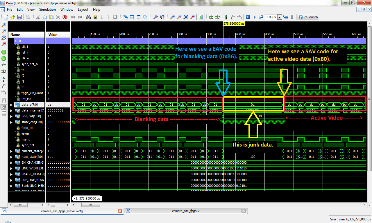
Bus (VIN1A[7:0]) looks like this:

SAV               Valid data                                          EAV

                  0  1  2  3  4  5  6  7......1276 1277 1278  1279       

FF  00  00  80    Y  U  Y  V  Y  U  Y  V......Y    U    Y     V       FF  00  00  9D

When we try to capture data the system hangs trying to dequeue frames.   My guess is that I have not successfully modified ti81xx_fb.c  for our configuration.   We have made the following changes to our configuration hdvpss_capture_sdev_info

.input_data_format = FVID2_DF_YUV422I_YUYV,

.ctrlChanSel = VPS_VIP_CTRL_CHAN_SEL_7_0,

.video_if_mode = VPS_CAPT_VIDEO_IF_MODE_8BIT,

Question:

1)      The video capture system should support this format. I have seen other posts that say it supports this format, but nowhere have I seen the required changes.


2)      Do I need to set a new v4l2_dv_preset for this 640x480.  If so, what value do I set.  If not, do I set it to INVALID and set the correct resolution when I send the ioctl command VIDIOC_S_DV_PRESET.


3)      Is there a tool that I can use to dump VIN configuration to see if it is configured correctly?


Thanks,

Craig

  • Hi,

    Craig Totel said:
    The video capture system should support this format. I have seen other posts that say it supports this format, but nowhere have I seen the required changes.

    Yes, Video capture supports this format and we are able tor receive 8-bit BT656 over VIN1 but with our Media controller driver and not V4L2 driver. Since V4L2 driver is not tested for BT656 it may involved some fine tuning.

    Craig Totel said:
    Do I need to set a new v4l2_dv_preset for this 640x480.  If so, what value do I set.  If not, do I set it to INVALID and set the correct resolution when I send the ioctl command VIDIOC_S_DV_PRESET.

    If you are calling S_DV_PRESET, than that is also fine. This is called to make sure that your buffer properties like height, pitch, width etc are set properly based on detected preset. You can just call VIDIOC_G_FMT to make sure that buffer is set properly after calling S_DV_PRESET.

    Craig Totel said:
    Is there a tool that I can use to dump VIN configuration to see if it is configured correctly?

    Yes, Can you dump 256 registers 0x48105a00. Attaching a tool to dump registers. You dump this once you do streamon. So open new telnet terminal and dump from there. you can use the attached app to dump registers.

    Make sure you are opening /dev/video2 node in case ti81xxvin.ko is loaded first and /dev/video5 incase ti81xxvo.ko is loaded first right?

    Regards,

    Hardik Shah

  • Hardik Shah,


    Thanks for the quick response.

    We are going down the path of using the V4L2 driver, since that is what the example capture programs are using.   Would it be possible to bypass this and use the Media controller driver that you reference?  We have a 640x480 camera connected to VIN1 and it is being configured through I2C by another microcontroller  (Not Linux) into the correct mode.  We are using this interface to take images at a slow rate.

    If we could use this other interface, could you point us to any examples that show using this interface.

    If  V4L2  is the way you recommend us to go, then we are planning on creating a dummy V4L2  sub-device driver that does nothing, but return the correct mode.  Does this seem reasonable?


    Thanks for the help/advice


    Craig

  • Hardik Shah,

     Some updates on the path we are going down...

     We are continuing  down the Video for Linux path and have created a dummy tvp7002 module that we are inserting just to configure the correct settings.  We have comment out the I2C reads/writes since our camera is configured by another processor.  We have hard code the following in the tvp7002_mbus_fmt:

     static int tvp7002_mbus_fmt(struct v4l2_subdev *sd, struct v4l2_mbus_framefmt *f)


            f->width = 640;

            f->height = 480;

            f->code = V4L2_MBUS_FMT_YUYV8_2X8;

            f->field =V4L2_FIELD_INTERLACED;

            f->colorspace = V4L2_COLORSPACE_REC709;


    We have made the following changes in the ti81xx_fb.c to reuse TVP7002_INST1 for initial testing for our camera:


                                    .name       = TVP7002_INST1,

                                    .board_info = {

                                                    I2C_BOARD_INFO("tvp7002", 0x5c),

                                                    .platform_data = &tvp7002_pdata,

                                    },

                                    .vip_port_cfg = {

                                                    .ctrlChanSel = VPS_VIP_CTRL_CHAN_SEL_7_0,

                                                    .ancChSel8b = VPS_VIP_ANC_CH_SEL_DONT_CARE,

                                                    .pixClkEdgePol = VPS_VIP_PIX_CLK_EDGE_POL_RISING,

                                                    .invertFidPol = 0,

                                                    .embConfig = {

                                                                    .errCorrEnable = 1,

                                                                    .srcNumPos = VPS_VIP_SRC_NUM_POS_DONT_CARE,

                                                                    .isMaxChan3Bits = 0,

                                                    },

                                                    .disConfig = {

                                                                    .fidSkewPostCnt = 0,

                                                                    .fidSkewPreCnt = 0,

                                                                    .lineCaptureStyle =

                                                                                    VPS_VIP_LINE_CAPTURE_STYLE_DONT_CARE,

                                                                    .fidDetectMode =

                                                                                    VPS_VIP_FID_DETECT_MODE_DONT_CARE,

                                                                    .actvidPol = VPS_VIP_POLARITY_DONT_CARE,

                                                                    .vsyncPol =  VPS_VIP_POLARITY_DONT_CARE,

                                                                    .hsyncPol = VPS_VIP_POLARITY_DONT_CARE,

                                                    }

                                    },

                                    .video_capture_mode =

                                                    VPS_CAPT_VIDEO_CAPTURE_MODE_SINGLE_CH_NON_MUX_EMBEDDED_SYNC,

                                    .video_if_mode = VPS_CAPT_VIDEO_IF_MODE_8BIT,

                                    .input_data_format = FVID2_DF_YUV422I_YUYV,

                    },


    When start the stream (/dev/video2) and then try and dequeue frames we are currently not getting any frames.  If we dump the registers we see the following:


    48105a00:  00000001 8000a110 00000000 00000000

    48105a10:  00000000 00000000 00000000 00000000

    48105a20:  ffffffff ffffffff ffffffff ffffffff

    48105a30:  00000000 00000000 00000000 00000000

    48105a40:  00000000 00000000 00000000 00000000

    48105a50:  00000000 00000000 00000000 00000000

    48105a60:  00000000 00000000 00000000 00000000

    48105a70:  00000000 00000000 00000000 00000000

    48105a80:  00000000 00000000 00000000 00000000

    48105a90:  00000000 00000000 00000000 00000000

    48105aa0:  00000000 00000000 00000000 00000000

    48105ab0:  00000000 00000000 00000000 00000000

    48105ac0:  00000000 00000000 00000000 00000000

    48105ad0:  00000000 00000000 00000000 00000000

    48105ae0:  00000000 00000000 00000000 00000000

    48105af0:  00000000 00000000 00000000 00000000

    So the setup is changing at least the first two registers, but since we can not find any documentation on these registers, not sure if they are correct.  Any advice/direction that you can point us to would be helpful....


    Craig

  • Hello,

    We are still struggling trying to figure out what we don't have configured correctly to see any data from our sensor.  Does the above register dump provide any information on what we may not have configured correctly.  We are opening /dev/video2 and currently not loading the ti81xxvo.ko, since from the users guide it does not appear required.

    We are not tied to using the V4L2 driver, if there is another method to interface to the capture module using the Media controller driver as mentioned in the response, we can try this. We have not found an example/documentation for using this interface. 

    Any help would be greatly appreciated!

    Thanks,

    Craig

  • Hi,

    Let me analyze your registers and get back to you.

    Regards,

    Hardik Shah

  • Hi,

    I analyzed registers. Registers are still configured to extract sync information from 15:8 lines instead of 0:7. It may be bug in vpss.c not modified properly for second instance or bug in driver, taking configuration from first instance. Can you debug this slightly further and see where problem lies.

    Regards,

    Hardik Shah

  • Hi Craig,


    I've been trying to follow the trail you're blazing here with respect to having a "decoderless" input by creating a dummy V4L2 driver and removing any I2C accesses.  Would you mind sharing your dummy driver and build process? (i.e., are you reworking the existing tvp7002 driver and kicking off a kernel build via 'make linux' from the top-level EZSDK directory?)

    I started off following the subdevice removal patches from this thread, but am starting to think a dummy subdevice driver might work out better.  I'd love to hear any insights you'd be willing to share!

    Thank you for your time and help.

    Jon

  • Hi,

    Instead of writing dummy subdev, i would suggest to remove all subdev calls from driver and wherever subdev returns some format or some preset, hardcode it to return from driver instead of subdev call.

    Regards,

    Hardik Shah

  • Hey Jon,

     I was also going down the path of stubbing out the sub device calls that was suggesting as a start.  After I had made the changes I could not get any data from our sensor.  I would call the dequeue data (ioctl-VIDIOC_DQBUF) and it would never return any frames.  Since, you have to make quite a few changes to stub out the calls and return values,  I was thinking that I may have screwed something up.

     We then decided that maybe creating a dummy tvp7002 driver would be less source code changes (less likely to mess it up).  I have attached the dummy driver.  It basically stubs out all the reads/writes over the I2C bus and returns the correct resolution/format in the sub call (tvp7002_mbus_fmt).  I can then load this dummy driver and get to the same point where I called the  IOCTL command to dequeue images and again no data.  Again, I am not sure if all the format is set correct, it is hard to tell with out knowing more about the HDVPSS registers.

     I then posted  registers dump that is in this earlier in this post and it appears that the control channels (.crtlChanSel) is not getting set correctly for our configuration.  After some debugging it looks like the driver or VPSS code is always using the .ctrlChanSel select registers for the embedded sync set in the first TVP7002_INST0.  If we set then both to user VPS_VIP_CTRL_CHAN_SEL_7_0, then it looks like the control bits are being set correctly.  We are still not getting data, see post below, so we are still not doing something correctly.

     Hope some of this helps

     Craig

     Also:

    To build the sub driver I pulled out the required files and am building as a module and then inserting it with ismod command.  The required files/makefile is in the attached zip.  You need to set the correct kernel path to your kernel source.   Again since we do not have this approach working, I can not say there are not issues with it.

    StubDriver.zip
  • Hardik,

     I have not found exactly what is the issue with my setup or the VPSS/driver code, but it looks like it is taking the configuration from TVP7002_INST0 for TVP7002_INST1.  If I set TVP7002_INST0 to have VPS_VIP_CTRL_CHAN_SEL_7_0, then when I open up the /dev/video2  the VPSS registers now  are configured differently.  I added some debug statements and it looks like the correct control code is now being passed. Can you look at the register dump below and see if it now has the correct control register specified.   I will look into this issue more, when I get a chance.

     But even with these new settings are we are still not getting any data from our sensor.  We call the IOCTL to dequeue data and get no frames.  We have verified the input signals into the video port are valid and the format we expect.

      Is there any more debug information that would point us to resolve our issue?  Is there any tools to dump configuration data or logging information from the video core?  With out some additional information, it is hard to know what we have configured incorrectly.

    For example, is the VPSS detecting the frames, but rejecting the frames for some reason?    


    Thanks,

    Craig


    New Register dump: (Initial post had configuration we are trying to read)

    48105a00:  00000002 8000a000 00000000 00000000
    48105a10:  00000000 00000000 00000000 00000000
    48105a20:  ffffffff ffffffff ffffffff ffffffff
    48105a30:  00000000 00000000 00000000 00000000
    48105a40:  00000000 00000000 00000000 00000000
    48105a50:  00000000 00000000 00000000 00000000
    48105a60:  00000000 00000000 00000000 00000000
    48105a70:  00000000 00000000 00000000 00000000
    48105a80:  00000000 00000000 00000000 00000000
    48105a90:  00000000 00000000 00000000 00000000
    48105aa0:  00000000 00000000 00000000 00000000
    48105ab0:  00000000 00000000 00000000 00000000
    48105ac0:  00000000 00000000 00000000 00000000
    48105ad0:  00000000 00000000 00000000 00000000
    48105ae0:  00000000 00000000 00000000 00000000
    48105af0:  00000000 00000000 00000000 00000000


  • Hi Craig -- thanks so much for the info!  I think I might start going this route soon, as the sub_devices_calls_removed.zip patches still leaves me with a few issues. As not to detract from the VIN1 issue discussion here, I've posted a follow up question over in the Regarding V4L2 drivers thread.

    Regards,

    Jon

  • I am working with Craig on this problem.  We have found that on the eval board, without driving TIM4_OUT (SYNC_DET on daughtercard) with a HSYNC like signal, one can not capture frames.  We are awaiting feedback from TI on if/where this is documented and how to get around this for an encoder that doesn't have the same signal.  We hope that embedded syncs are supported without the need to drive this pin, but are awaiting some help with this.

  • Hi,

    We have forwarded your query to our local board team here. Waiting for their reply. Embedded sync capture without that pin should also be supported.

    Regards,

    Hardik Shah

  • Hardik,

    We saw this behavior (with TIM4) a few days ago, but now are unable to reproduce the behavior.  Yesterday we were able to capture from a FPGA without driving TIM4.  That may be a false alarm.  It still would be good to know if this pin is used on the reference design/with the M3 core.

    - Thad

  • Anyone who can help...

    We have noticed that when we are capturing, the register at address 0x48105a30 has the size of the image we are trying to capture.  With our current setup, the first four hex digits = the width/2, while the second four hex digits = # of lines.  So for a 640 x 480 image, we would get:

    48105a30:  014001E0

    We are able to capture into the eval board with this through a FPGA and our camera.  The FPGA is basically passing the signals through.

    On our board we see the following.  Our camera is putting out a 636 x 480 image.  The register at 0x48105a30 outputs the correct line width of 318 (636/2), but the # of lines continuously increments by 480 (so counts 0x1E0, 3C0, 5A0, etc with rollover) .  This makes me think that whatever interfaces to these registers is capturing data.  Does anyone have an idea what would cause this behavior and how we can get HDVPSS/TI code to pass us a frame?

    We can't figure out what we are doing wrong.

    - Thad

  • Hi,

    I  have forwarded your question to hardware engineer here. Waiting for their reply.

    Regards,

    Hardik Shah

  • For everyone who can't sleep at night because of the VIP and is following this post...  :)

    We think that the reason we are getting rollover in the lines portion of the memory dump is because of the data our sensor (OV7740) is putting out.  I have attached a FPGA simulation that depicts what the data from our camera looks like.  This seems to cause the TI core to hang while capturing and the counter to roll over.  I have seen that if the SAV code in the picture is for blanking data, the TI core will still capture.  This is what we have seen using a FPGA we wired into the evaluation board to simulate our camera.  It captured fine until I added this junk data to it's output.

    There is one other observation we made while debugging.  We haven't definitely proven this, but with a line length not divisible by 4, the TI core/driver/something seemed to hang.  The OV7740 was also conveniently putting out 1279 bytes/line in YUV mode, which seemed to break things.

    Have fun!  If you're really stuck, I think Craig and I would recommend finding yourself a FPGA and someone who knows Verilog to try things to see what breaks the TI core and what works.  Half the errata on this device (the 8168) seems to pertain to the VIP core.

    - Thad

  • Hi All, 

    I am having a similar problem with the TIM4_OUT signal, causing problems to capture video properly (see description of my problem here http://e2e.ti.com/support/dsp/davinci_digital_media_processors/f/717/p/171165/863084.aspx#863084).

    Could someone provide the tool to dump the configuration registers of the VIN port? I noticed that it was mentioned in this post but I didn't find from where I can download it.

    Thanks,

    -David

  • Hi,

    I did not get it. Are you seeing hang? Is the uart responding? 

    VIP works in the detection mode, so whenever it sees SAV or EAV code, it marks that line/frame as started or ended. so if you have very long data between, it could roll over the counter and it could corrupt the memory as well. 

    Regarding the divisible by 4 creating the issue, could you please tell us which release are you using? We have some fixes for this issue.

    Regards,

    Brijesh Jadav

  • Hi Brijesh, 

    In my case I am using the EZSDK 5.05.01.04 with the DM816x-EVM.

    I am trying to capture from component using embedded sync signals so I shouldn't need the TIM4 (sync signal in the EVM schematics). For instance when the SoG is enabled I am able to run the pipeline without problems.

    However, If I disable the SoG signal which is connected to the TIM4 pin the pipeline starts but after some buffers it says that it can't get more frames so the pipeline is closed.

    I need to remove this dependency on the SoG signal since I am trying to do Dual Capture on the EVM (http://e2e.ti.com/support/dsp/davinci_digital_media_processors/f/716/p/160009/852138.aspx#852138) which already works but not from gstreamer, so I was wondering which is the dependency of this signal.

    It it pretty easy to check this, for instance, boot your EVM and and run the following pipeline:

    gst-launch v4l2src device=/dev/video0 always-copy=false queue-size=12 ! 'video/x-raw-yuv-strided,format=(fourcc)NV12,width=1920,height=1080,framerate=(fraction)60/1' ! omxbufferalloc numBuffers=12 ! omx_scaler ! gstperf ! v4l2sink sync=false -v

    it will run ok, now disable the SoG signal (just change the mode of the TIM4)

    Enable or disable the SoG

    mount -t debugfs none /sys/kernel/debug

    cd /sys/kernel/debug/omap_mux

    echo 1 > tim4_out

    and try to run the pipeline again, it won't work.

    Thanks for your help in advance, also if you can provide the tool to dump all the vin registers would be great!

    -David

  • Hi David,

    Since you are using latest EZSDK, it has fix for line size not divisible 4 issue. so you will not see this issue.

    I could not understand how your decoder is connected to the input port. I think you are connecting component input to the decoder line TVP7002, which will decode analog signal and provide BT1120 embedded sync signal to the input port. So if you enable or disable sync on green, you will have to change decoder accordingly so that it can detect input standard correctly and send the correct data to input port. 

    Thanks,

    Brijesh Jadav

  • Hi Brijesh,

    First, thank you for your help on this.

    Since I am using the DM8168-EVM to capture component, yes, the component input is connected to the decoder TVP7002, it decodes the analog sinal and it provides the video with the embedded sync signals to the input ports. So, the SoG is not needed, however the TVP7002 has the ability to generate it and it will be present in the SoG pin of the TVP.

          When I say that I enable or disable the SoG signal, means that I need to disable the U66 chip on the schematics (http://support.spectrumdigital.com/boards/evm816xiodc/revc/files/evm816xiodc_Schematics_RevC.pdf), this basically because by default the U66 is enabled from the board file, causing a problem if you want to use both TVP7002 (present on the EVM) at the same time. (you would have both SoG signals at the outputs of the U66 and then they will end in the same cable according to the schematics). Full description here: http://e2e.ti.com/support/dsp/davinci_digital_media_processors/f/717/p/171165/863084.aspx#863084

       If I disable the U66 (no SoG signal going to the netra), I cannot capture using gstreamer, it captures 10 buffers and then the driver is not able to dequeue buffers, the pipeline works if SoG is enabled.

    However, this doesn't happens with the saLoopBack application, so I was wondering if you know what is the need to drive the SoG signal or TIM4 pin of the netra? Sometime really weird is that according to the pinmux the pin is configured as output and is connected as an input.

    register value for tim4
    A)

    /sys/kernel/debug/omap_mux # cat tim4_out
    name: tim4_out.tim4_out (0x48140b28/0xb28 = 0x0000), b NA, t NA
    mode: OMAP_PIN_OUTPUT | OMAP_MUX_MODE0
    signals: tim4_out | gp0_io28 | NA | NA | NA | NA | NA | NA

    B)

    /sys/kernel/debug/omap_mux # devmem 0x48140b28

    0x00000000

    Thanks in advance,

    -David

  • Hi David,

    I am not sure what is the use of the TIM4_OUT pin. I will check it out and get back to you.

    So when the capture stops capturing after 10 frames, can you please check if there is any overflow in the VIP? or can you provide the value at the address 0x4810551C? If there is any overflow, we will have to stop and reset the input port. I am not sure if this is taken care in your code. Could you check in the saLoopback application how it handles this overflow condition and use the same in your application?

    Regards,

    Brijesh Jadav

  • Hi Brijesh,

    Thanks for your help on this again. The saLoopBack application has some code to handle when there is an overflow on the port, however, when this happens it should show a message:

    /* If DQbuf returned error check for the hardware lockup
    */
    ret = ioctl(capt.fd, TICAPT_CHECK_OVERFLOW, &capt.over_flow);
    if (ret < 0) {
    perror("TICAPT_CHECK_OVERFLOW\n");
    return -1;
    } else {
    /* If hardware locked up, restart display and
    * capture driver
    */
    if (capt.over_flow.porta_overflow) {
    printf("Port a overflowed\n\n\n\n\n\n\n");
    stopCapture();
    stopDisplay();
    goto restart;

    }
    if (capt.over_flow.portb_overflow) {
    printf("Port b overflowed\n\n\n\n\n\n\n");
    stopCapture();
    stopDisplay();
    goto restart;
    }
    }

    I never get this message so there is no overflow present in the test.

    Moreover, I read the value of the registers, here is what I did:


    when I boot the board it always has:

    / # devmem 0x4810551C
    0x00000000

    Then I read the register when using gstreamer and when using the saLoopBack application. Always capturing from /dev/video0 which is the VIP0.

    * With the saLoopBack application

    a) Boot the board with the SoG (TIM4 enabled/echo 0 > tim4_out). Then I run the saLoopBack application and read the 0x4810551C register

    / # devmem 0x4810551C
    0x00000400

    b) Then I disabled the SoG signal (TIM4 disabled/echo 1 > tim4_out) and read the 0x4810551C register, both, before to run the saLoopBack and after, getting the same value in these cases:

    # devmem 0x4810551C
    0x00000404

    In a) and b) saLoopBack works without problem.

    * With Gstreamer

    a) Boot the board with the SoG (TIM4 enabled/echo 0 > tim4_out). Then I run the gstreamer pipeline and read the 0x4810551C register

    / # devmem 0x4810551C
    0x00000400

    b) Then I disabled the SoG signal (TIM4 disabled/echo 1 > tim4_out) and read the 0x4810551C register, both, before to run the pipeline and after

    Before run the pipeline:

    # devmem 0x4810551C
    0x00000400

    After run the pipeline:

    # devmem 0x4810551C
    0x00000414

    In this case since the SoG signal is disabled the pipeline hangs after some buffers.

    Since there is not documentation about the video input port registers I don't know which addresses I should check, However, according to Hardik (http://e2e.ti.com/support/dsp/davinci_digital_media_processors/f/717/t/165987.aspx?pi239031349=1) he recomends to check the 256 registers starting on 0x48105a00, I did a dump of this registers (see attached file) and these doesn't change when using gstreamer or saLoopBack.

    Also in other post on the E2E I found a guy who check the registers from

  • Hi David,

    There is no overflow when you run loopback application, but there is an overflow when you run gStreamer application. And there is an overflow, we have to reset input port, otherwise it stops giving output. So when you don't get any frames, could you please try resetting input port?  This should recover input port and you should start getting frames in the application.

    Regarding documentation for the register, you will have contact your local TI FAE.

    Regards,

    Brijesh Jadav

  • Hi Brijesh,

     Yes, I would suppose that that value 0x00000414 means an overflow on the port (not sure what means each bit on this register), however, this overflow is being caused by the absence of the SoG signal, because using gstreamer with the SoG enabled I can use the pipeline without problems and the value for this register is 0x00000400 in this case. 

    Do you have an idea which is the function of the TIM4 pin? or why there is an overflow if the SoG signal (TIM4 pin) is not present?

    Thanks for your nice help on this Brijesh!

    -David

  • Hi David,

    As far as i know, this pin can also be used as a GPIO pin. I am not OMX expert, may be OMX is using it as GPIO to detect sync status, does something like stopping the driver when it does not detect the sync on this pin. 

    Overflow could come because of many reasons, like your input signal is not stable or your are using in line scalar and input receives short frame or dma engine is not able to write that fast. So if one of these condition occurs, there could be overflow and we have to call reset and restart ioctl in order to recover from overflow.

    regards,

    Brijesh Jadav

  • Hi Brijesh,

             Thanks for your comments. For the time being I am using a very simple pipeline which works when the SoG signal is enabled, also I am not using OMX to capture since I am using the V4L2 capture driver:

    gst-launch v4l2src device=/dev/video0 always-copy=false queue-size=8 ! 'video/x-raw-yuv-strided,format=(fourcc)YUY2,width=1920,height=1080,framerate=(fraction)60/1' ! omxbufferalloc numBuffers=8 ! fakesink -v

    So OMX could not be the problem. Moreover I found a description of the TIM4_OUT pin on the datasheet (http://www.ti.com/lit/ds/sprs614d/sprs614d.pdf)

    On page 90:

    "Timer4 capture event input or PWM output" - Page 90 

    On page 305:

    "Dedicated input trigger for capture mode and dedicated output trigger or pulse width modulation(PWM) signal

     Interrupts generated on overflow, compare, and capture"

    So it seems that the signal is used as a trigger but I don't know why the saLoopBack application works and gstreamer doesn't (since I am using embedded sync signals). Anyway I found that the V4L2 capture driver has a timer called inst->overflow_timer which periodically calls to ti81xxvin_overflow_handler which checks if there is an overflow (using the ti81xxvin_check_overflow function), this function checks a register (which seems to be the same 0x4810551C), specifically the bit number 5, (VIP_PARSER_FIQ_STATUS_OUTPUT_FIFO_PRTA_LUMA_STATUS_MASK), if it set on 1 then it reports an overflow. As you know I got a 0x00000414 from this register, so the bit number 5 is on 1 and that is why gstreamer detects an overflow.

    On this register, I noticed that when I disable SoG I get a 0x00000404 instead of the expected 0x00000400, what is the meaning of the bit number 3 on this register?


    I will continue working on this and let you know my progress. I can not be restarting the port...

    Thanks,

    -David


  • Hi David,

    Could you please look into the OMX application and check what it does when it gets this event? If you are not seeing overflow in V4L2 driver, you should not get it on OMX as well. Could you please also let me know what other modules are getting used in the input port? Are you enabling inline scalar?

    Regards,

    Brijesh Jadav

  • Hi David,

    Could you also check if the value at the offset 0x481055D8 and 0x481055DC (or 0x48105AD8 and 0x48105ADC for VIP1) is set to 0xFFFFFFFF? If not set, could you please set it and try it out?

    Regards,

    Brijesh Jadav

  • Hi Brijesh!

         I read the registers and they were not in 0xFFFFFFFF, then I tried to set them to the correct value, however, after that I tried to read and they are all in 0 again, this was the sequence of commands:

    / # devmem2 0x481055D8
    /dev/mem opened.
    Memory mapped at address 0x403a9000.
    Value at address 0x481055D8 (0x403a95d8): 0x0


    / # devmem2 0x481055D8 w 0xFFFFFFFF
    /dev/mem opened.
    Memory mapped at address 0x40259000.
    Value at address 0x481055D8 (0x402595d8): 0x0
    Written 0xFFFFFFFF; readback 0xFFFFFFFF

    / # devmem2 0x481055D8
    /dev/mem opened.
    Memory mapped at address 0x4017a000.
    Value at address 0x481055D8 (0x4017a5d8): 0x0

    / # devmem2 0x48105ADC
    /dev/mem opened.
    Memory mapped at address 0x403ca000.
    Value at address 0x48105ADC (0x403caadc): 0x0

    / # devmem2 0x48105ADC w 0xFFFFFFFF
    /dev/mem opened.
    Memory mapped at address 0x400b3000.
    Value at address 0x48105ADC (0x400b3adc): 0x0
    Written 0xFFFFFFFF; readback 0xFFFFFFFF

    / # devmem2 0x48105ADC
    /dev/mem opened.
    Memory mapped at address 0x401c7000.
    Value at address 0x48105ADC (0x401c7adc): 0x0


    It seems that something is changing the values again or devmem can't set them. Checking the TRM and the datasheet it seems that these registers are part of the set of register for the HDVPSS. Why these have to be on 0xFFFFFFFF?

    Also, my application is the pipeline:

    gst-launch v4l2src device=/dev/video0 always-copy=false queue-size=8 ! 'video/x-raw-yuv-strided,format=(fourcc)YUY2,width=1920,height=1080,framerate=(fraction)60/1' ! omxbufferalloc numBuffers=8 ! fakesink -v

    So at this moment I am not using OMX components, just the V4L2 capture driver is involved.

    Thanks for your comments Brijesh, for me it seems that you already have a clue about what is the problem! looking forward to hear your comments about these registers.

    What about the bit number 3 on the register 0x4810551C? is this a clue?

    -David

  • Hi,

    I got the dual capture working with gstreamer as well. I was having problems with the EVM so I switched to the customer's hardware which has a FPGA feeding video into a DM8168 z3 module, which we got working. Switching back to the EVM hardware, we solved the problem that is related to the TVP7002 configuration (H-PLL Control register) to capture 1080p. On the RidgeRun developers wiki you will find the patch (https://www.ridgerun.com/developer/wiki/index.php/Getting_Started_Guide_for_DM8168_EVM#Dual_V4L2_Capture_Patch) to add this support.

    RidgeRun's customer required a dual capture solution so we also solved a problems to allow them to run two gstreamer capture pipelines simultaneously.

    -David

  • Hi

    I am doing as follew:

    1 st :using CMOS sensor to capture image

    2 nd: DM8168 reciev these image directly

    3 rd: the capacity of the CMOS sensor is up to 5M ,just like MT9P031

    but I cannot capture these image using DM8168 directly, is there any solutions for this situation?

  • Hi John,


    Is this RAW sensor? please note that VIP does not support RAW capture, there is no way to convert RAW to actual RGB or YUV data in VIP.

    Which resolution are yoo trying to capture? what is your input interface?


    Regards,

    Brijesh Jadav

  • 1 st:  sensor is raw sensor

    2 nd: all above is meaning to improve the resolution of the video source , Boss ask me at least 5M

    2 nd: may I use FPGA to  convert  raw data to RGB or YUV  in this situation  /OR What's your suggestion to  improve resolution

  • Hi,


    So first is there is no module in VIP to convert RAW to YUV, so having FPGA to convert RAW to YUV is better option. Second, VIP can support at max 1080p resolution and at max 165MHz pixel clock, so it may not be able to support 5M resolution? when you say 5M, could you tell me what is the exact resolution?


    Regards,

    Brijesh

  • Thank U for your answer!

     "5M" means : the pixel value of the camera is 5M . Sorry for this mistake. 

    1     is there any method to capture video whose pixel value more than 5M without FPGA

    2   could U afford some documents  for describing  VIN of DM8168 ,  alsosome reference design suggestion  for  implementing "1" 


  • hi Jhon,

     "5M" means : the pixel value of the camera is 5M . Sorry for this mistake. 

    - does 5M mean "2,560×1,920" ?? if yes, it's out of the restriction of VIP due to 165MHz(1920x1200).

  • Hi Jack

    thank U for answer!

    No ,  pixel value of the camera is 5M , resolution of the video is 1080p ,