AM62L-EVSE-DEV-EVM: No WL1837 MODULE response

Part Number: AM62L-EVSE-DEV-EVM
Other Parts Discussed in Thread: WL1837, SK-AM62, , WL1837MOD, AM62L

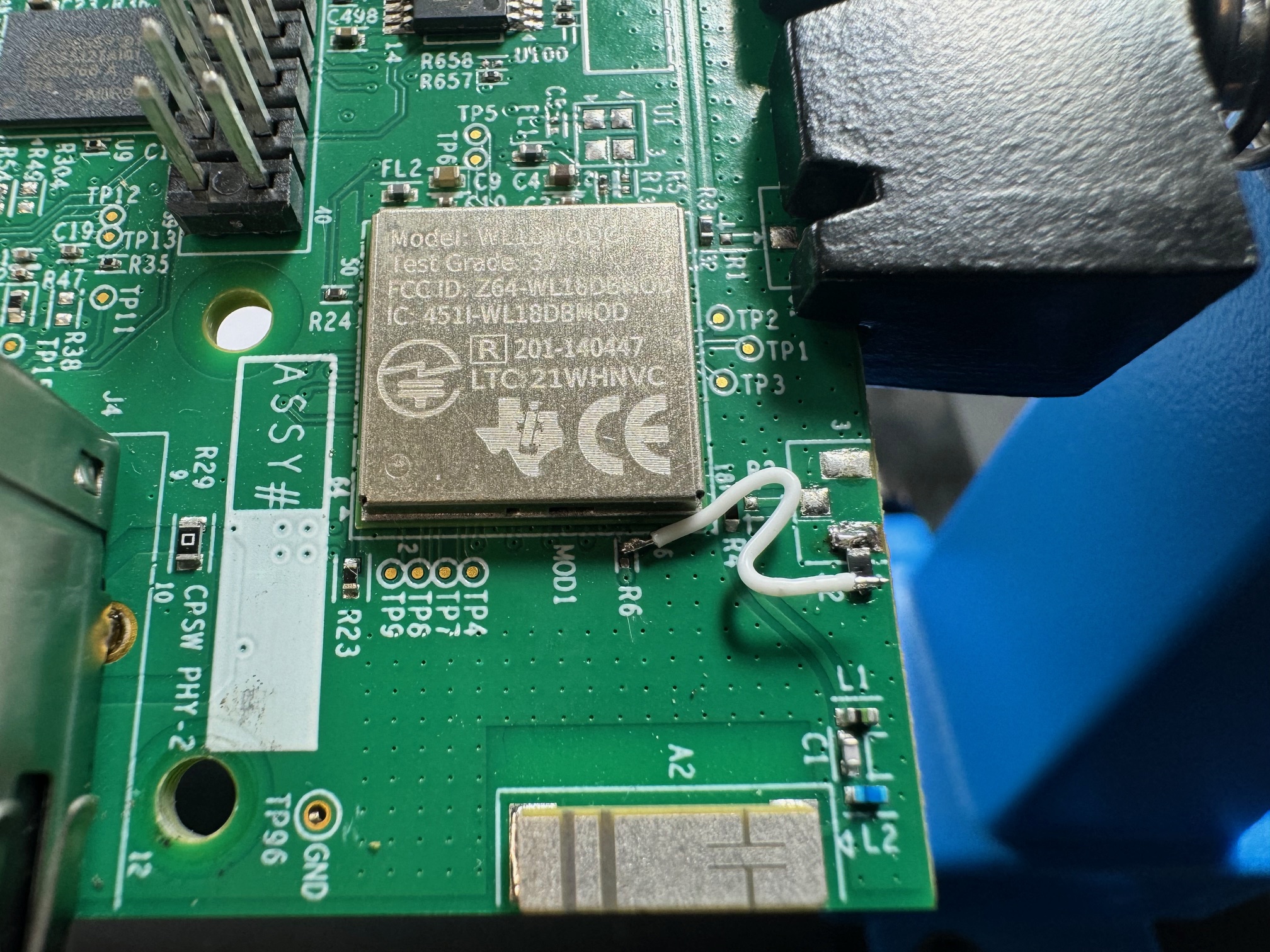
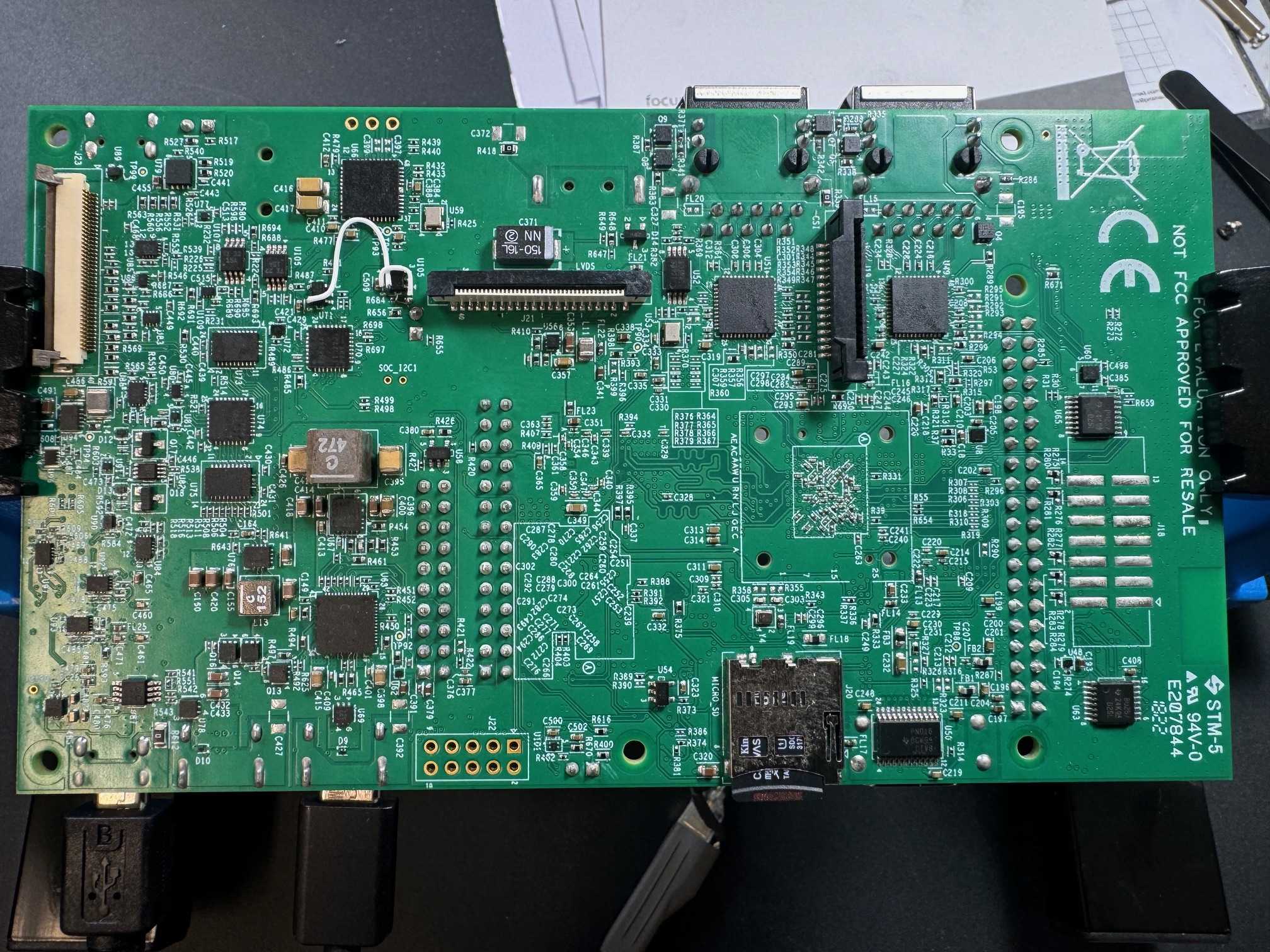
Dear All, For several days now, we've been trying to get communication working on our recently purchased EVM SK-AM62, an AM62x starter kit for Sitara™ processors. The HDMI and LCD outputs are enabled via LVDS, and after hardware changes, the touchpanel also works. Unfortunately, we're unable to get the WL1837 module to work. The module doesn't respond via CMD or IRQ. It receives the correct power sequence: a slow CLK of 32kHz, followed by raising the WLAN_EN state. MMC2_CLK 400kHz is present, along with packets sent to MMC2_CMD by the host. There's no activity on WLAN_IRQ (fixed 1.8V) and no responses to MMC2_CMD. As part of our testing, we decided to desolder resistor R6 PU to VCC1_8 WLAN_IRQ. Voltage monitoring shows a floating reading of about 0.4V. Tests involving setting the AM62 MMC2_SDWP B23 pin as an output and forcing voltage control on the desoldered R6 resistor pad yielded no results. It's as if there were no physical connection between the MCU and the WL1837 via WLAN_IRQ. Hence the question: has the EVM been tested for communication with the WL1837? What can you advise in this situation? Kind regards, MariuszIMG_8855.jpgIMG_8856.jpgIMG_8857.jpgIMG_8858.jpg
  • Hello Mariusz,

    Thank you for your query !

    Please allow me some time to look into. I will get back with a response early next week.

    Thank you for your patience

    Best Regards,

    Anastas Yordanov

  • Hello Mariusz,

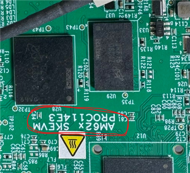
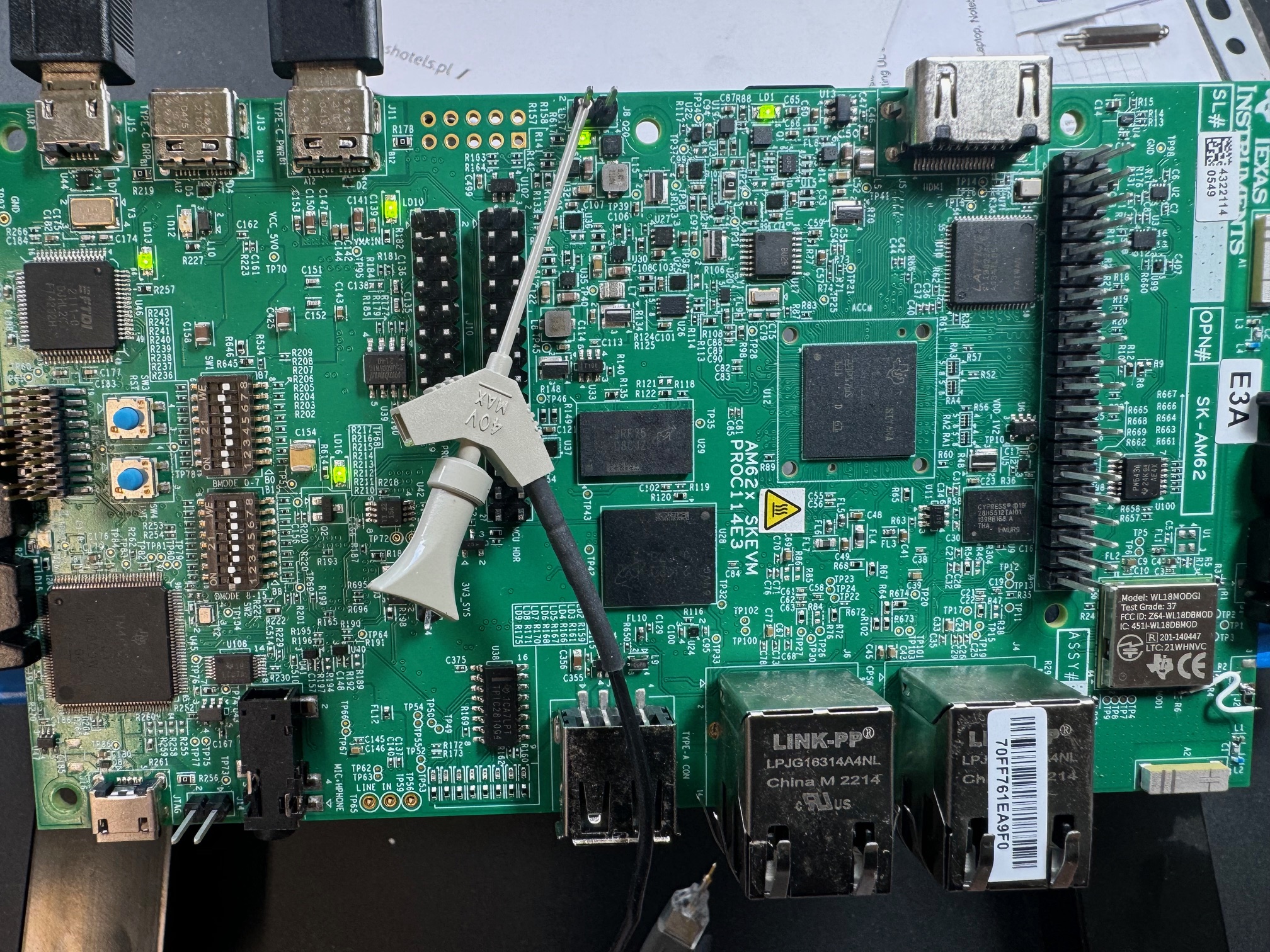
    I'd like to apologize for the big time gap in my respone. I suppose that the used TAG: AM62L-EVSE-DEV-EVM is unrelated to this issue. Please confirm ? From the EVM board's picture:

    I see this is the AM62x-SKEVM. The schematic design is sprr448 / PROC114-E3.

    The SDIO hardware interface is implemented on the AM62x MMC2 port. 

    Q1: Did you have the chance, with all circuits powered-off, to measure with a multimeter just the resistance between the output pin 14 (MOD1A) of the WL1837MODGIMOCT and the AM62x pin MMC2_SDWP (ball B23) ? According to the schematic, there should be a short between these two points.

    I suspect that removal of the R6 external pull-up to the 1.8V power supply and the floating 0.4V level present after this re-work step, could mean not ONLY a weak connection between MOD1A and the AM62x pin MMC2_SDWP (GPIO0_72 input) but also, a tri-stated (for some reason) interrupt output of the WL module.

    Q2. So I have an important question: Were you able to see 1.8V high level (inactive line), measuring directly on the WL1837MODGIMOCT pin MOD1A after removal of the R6 pull-up resistor ?

    Q3. Are these white wire reworks related to the WLAN ?

    As an initial step you can check the pin-mux configuration initial settings of the AM62x Control module PADCONFIG74 register. Please make sure that the PADCONFIG74 controlled INPUT buffer of the AM62x.MMC2_SDWP pin is enabled via bit RXACT=0b1. The pin weak pulls shall be disabled. 

    The GPIO0_72 signal is connected to the "GPIOMUX INTROUTER0" Interrupt Router input MAIN_GPIOMUX_INTROUTER0_IN_IN_72. Have you observed any GPIO0_72 GPIO interrupt event status register changes.

    Would you please specify the type and SDK version you use, in case I need to approach the SDIO software developer. 

    Thank you !

    Best Regards,

    Anastas Yordanov 

  • Hi, Anastas,

    First, I apologize for the typo: AM62L-EVSE-DEV-EVM. That's unrelated. My bad. Absolutely, this is the AM62x-SKEVM. The schematic design is from source SPR448 / PROC114-E3.

    Q1: Pin 14 (MOD1A) of the WL1837MODGIMOCT and the AM62x pin MMC2_SDWP (ball B23) are on the underside of both chips' packages. I don't have access to them. The only access is PAD R6 and maybe some vias. I could measure the trace using the nearest vias (if available), but I don't have a PCB design (e.g., Altium) to figure out which is which. If you send me the Altium design, I'll try to find them and measure more and give you a more precise answer. The tri-stated (for some reason) interrupt output of the WL module is also something that puzzles me greatly.

    Q2: Not at all. After removing the R6 pull-up resistor, it floats all the time.
    Q3: No, the white wires are a known touchpad interface rework error. Described in the EVM User's Guide.

    pin-mux configuration - checked and even changed PU/PD to see the result. I will try again to be 100% sure. I will get back with an answer.

    Have you observed any GPIO0_72 GPIO interrupt event status register changes - never observed an interrupt event. Of course, the oscilloscope also doesn't trigger on this output.

    If I remember correctly, we use this image for the first hardware boot: tisdk-default-image-am62xx-evm-12.00.00.07.04.rootfs.wic.xz — 1224653 K.
    Regards, Mariusz

  • Hi Mariusz,

    Thank you very much for answering my questions and providing the software info. 

    I could measure the trace using the nearest vias (if available), but I don't have a PCB design (e.g., Altium) to figure out which is which. If you send me the Altium design, I'll try to find them and measure more and give you a more precise answer. The tri-stated (for some reason) interrupt output of the WL module is also something that puzzles me greatly.

    I understand. Unfortunately, there seem to be no TPs associated with WLAN_IRQ signal on both sides, and no way to test the connection with a multimeter. But the constant presence of floating 0.4V after you removed the pull-up maybe quite indicative, that the pin 14 stays HiZ for some reason. Can you confirm that you observe that the CMD line remains permanently asserted HIGH after you send a valid SDIO command from the MMC2 host to the WLAN device ?

    Please allow me some time to research in the WL1837 datasheet what may cause this "device-failed-to-initialize" like behavior - because you said that you do not obtain a response by the WLAN on the CMD line.

    I'll try to respond early next week.

    Thank you !

    Best Regards,

    Anastas Yordanov  

  • Hi Mariusz,

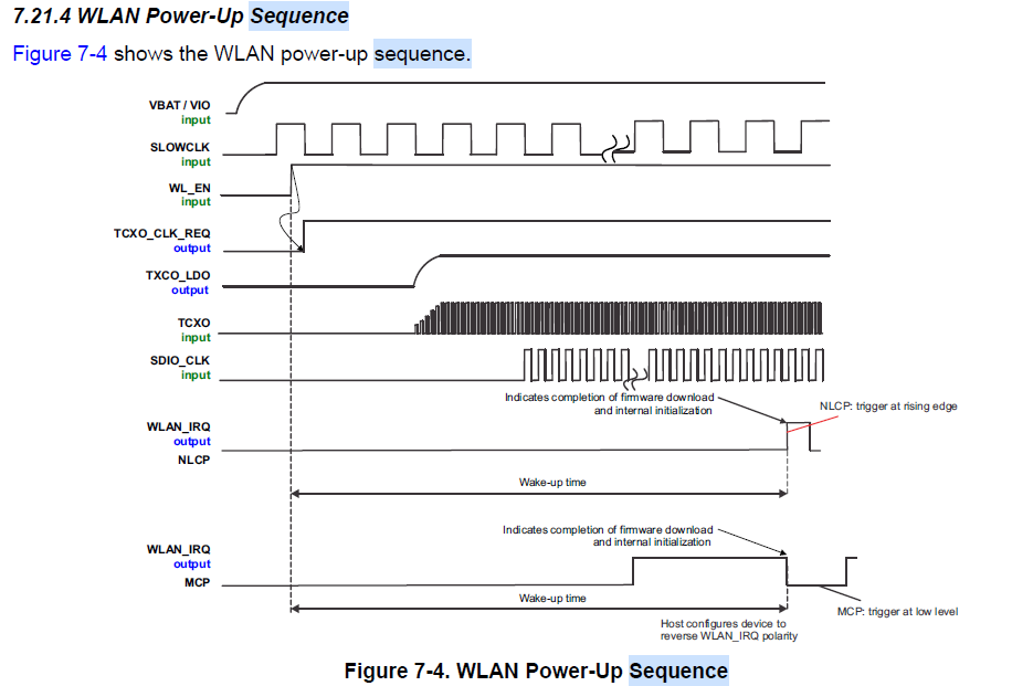
    Can you confirm the design respects the WL1837MOD Power-up and down sequences in terms of their recommended timings, as described in the WL1837 datasheet:

    And from below Wireless LAN Power-up sequence, the exact moment when WLAN_IRQ gets activated (where IRQ configured as active HIGH on pre-last diagram, or active LOW on the last diagram ) is when device firmware downloaded and initialization successfully finished.

    The module doesn't respond via CMD or IRQ. It receives the correct power sequence: a slow CLK of 32kHz, followed by raising the WLAN_EN state. MMC2_CLK 400kHz is present, along with packets sent to MMC2_CMD by the host. There's no activity on WLAN_IRQ (fixed 1.8V) and no responses to MMC2_CMD.

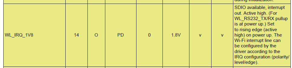
    Restoring back the 10k pull-up to the WLAN_IRQ, can you confirm that you are constantly measure a HIGH LEVEL (fixed at 1.8V), starting from the very initial moment of powering up the AM62L and WL1837MOD circuits to the first SDIO host CMD. Have you verified this via some scope measurement of WLAN_IRQ signal, synchronizing to the VCC1V8 power supply rising transition ? As per the below WL1837 Datasheet table, Section Pin Attributes, the WLAN_IRQ should be configured as "ACTIVE HIGH" by default (rising edge event). I expect to see that WLAN_IRQ = "LOW" until the internal initialization over the SDIO interface is finished. A successful  initialization completion shall be followed by a rising edge transition LOW -> HIGH on the AM62L.MMC2_SDWP input pin.  

    One more thing to add: From the Pin attributes table, there seem to be an internal pull down on the WL_IRQ_1V8. I think that in such case, from shut down state throughout the wake-up period, you should have measured a different level < 1.8V on the WL1837MOD pin 14 because of voltage divider that formed between your external pull-up resistor R6 and the internal pull-down resistor. Can you confirm this via above suggested measurement ? If not, this means that the pull-up 10k resistor may have a "bad-junction" contact with the WLAN_IRQ line. Please verify the junction between the resistor and the PCB pad. Is there a chance that the PCB trace has been lifted ?

    Apart from this, if there is no command response from the WL1837 after the very first SDIO command, you can NOT expect the WL_IRQ_1V8 to trigger, as the SDIO device should have to be successfully configured over SDIO bus first (as per my understanding from the datasheet).

    I hope this helps !

    Let me know what your thoughts are.

    Thanks

    Best Regards,

    Anastas Yordanov