DRA821U: How to change eMMC frequency?

Part Number: DRA821U
Other Parts Discussed in Thread: DRA821

Hi there,

We are using J7200 SDK v10.0 for our DRA821 custom board and want to change eMMC frequency from default 200MHz to 150MHz. What kind of changes in SDK should I make to implement this?

Thanks,

Charles

  • Hi Charles,

    The below patch should limit the frequency to 150 Mhz.

    diff --git a/arch/arm64/boot/dts/ti/k3-j7200-common-proc-board.dts b/arch/arm64/boot/dts/ti/k3-j7200-common-proc-board.dts
    index 735ffd3f3..adde5f619 100644
    --- a/arch/arm64/boot/dts/ti/k3-j7200-common-proc-board.dts
    +++ b/arch/arm64/boot/dts/ti/k3-j7200-common-proc-board.dts
    @@ -396,6 +396,7 @@ &main_sdhci0 {
            bootph-all;
            ti,driver-strength-ohm = <50>;
            disable-wp;
    +       max-frequency = <150000000>;  /* Limit to 150 MHz */
     };
     
     &main_sdhci1 {

    Output log(LInux kernel):

    Best Regards

    Gokul Praveen

  • Hi Gokul,

    Thanks for your support. I tried your suggestion but it still show 200MHz as shown below

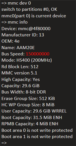
    However, I did see some changes in U-Boot as highlighted below. It was 200000000 before I rebuilt the image with your suggestion.

    Here's related device trees configurations.

    k3-j7200-comm-proc-board.dts

    &main_sdhci0 {
            /* eMMC */
            status = "okay";
            non-removable;
            ti,driver-strength-ohm = <50>;
            disable-wp;
            max-frequency = <150000000>;  /* Limit eMMC frequency to 150MHz */
    };

    k3-j7200-main.dtsi

            main_sdhci0: mmc@4f80000 {
                    compatible = "ti,j7200-sdhci-8bit", "ti,j721e-sdhci-8bit";
                    reg = <0x00 0x04f80000 0x00 0x260>, <0x00 0x4f88000 0x00 0x134>;
                    interrupts = <GIC_SPI 3 IRQ_TYPE_LEVEL_HIGH>;
                    power-domains = <&k3_pds 91 TI_SCI_PD_EXCLUSIVE>;
                    clock-names = "clk_ahb", "clk_xin";
                    clocks = <&k3_clks 91 0>, <&k3_clks 91 3>;
                    ti,otap-del-sel-legacy = <0x0>;
                    ti,otap-del-sel-mmc-hs = <0x0>;
                    ti,otap-del-sel-ddr52 = <0x6>;
                    ti,otap-del-sel-hs200 = <0x8>;
                    ti,otap-del-sel-hs400 = <0x5>;
                    ti,itap-del-sel-legacy = <0x10>;
                    ti,itap-del-sel-mmc-hs = <0xa>;
                    ti,itap-del-sel-ddr52 = <0x3>;
                    ti,strobe-sel = <0x77>;
                    ti,clkbuf-sel = <0x7>;
                    ti,trm-icp = <0x8>;
                    bus-width = <8>;
                    mmc-ddr-1_8v;
                    mmc-hs200-1_8v;
                    mmc-hs400-1_8v;
                    dma-coherent;
                    status = "disabled";
            };

    Please advise the next step.

    Thanks,

    Charles

  • Hi Charles,

    I believe that you had applied the changes to the k3-j7200-common-proc-board.dts present in uboot directory.

    The below patch should limit the frequency to 150 Mhz.

    Instead, please apply the changes in <Linux kernel directory>/arch/arm64/boot/dts/ti/k3-j7200-common-proc-board.dts, rebuild the dts and copy the dtb(k3-j7200-common-proc-board.dtb) to the <rootfs directory of bootmedia>/boot/dtb/ti/ directory .

    Can you also share the files in <rootfs directory of bootmedia>/boot/dtb/ti directory?

    Best Regards

    Gokul Praveen

  • Hi Gokul,

    Even I configured to 150MHz, but the scope measured clock is only 100MHz.

    root@edr:~# cat /sys/kernel/debug/mmc0/clock
    150000000

    root@edr:~# cat /sys/kernel/debug/mmc0/ios
    clock: 150000000 Hz
    actual clock: 100000000 Hz
    vdd: 7 (1.65 - 1.95 V)
    bus mode: 2 (push-pull)
    chip select: 0 (don't care)
    power mode: 2 (on)
    bus width: 3 (8 bits)
    timing spec: 10 (mmc HS400)
    signal voltage: 1 (1.80 V)
    driver type: 0 (driver type B)

    How to get actual clock 150MHz?

    Thanks,

    Charles

  • HI Charles,

    Thank you for your prompt response.

    I now digged depper and found out that 150Mhz cannot be achieved because the way output clock frequency is achieved is using the following formula:

    • div >= input clock(200Mhz)/clock(150Mhz) 
      • Here, div>=1(ie:200/150)
    • actual_clock = Input clock(which is 200Mhz) / div.

    As there is no input clock with 150Mhz, the only possible actual clock values are 200Mhz(200/1), 100Mhz(200/2) and so on.... 

    Best Regards

    Gokul Praveen

  • Hi Gokul,

    Thanks for your reply. I have a few more questions:

    1. Can we change input clock to something other than 200MHz? for example, select a different input clock source, or configure PLL to change input clock frequency away from 200MHz? If yes, how?

    2. Can div=3? If yes, how to change div in software?

    3. Can we modify eMMC driver code to hard-code 150MHz? If yes, how?

    Thanks,

    Charles

  • Hi Charles,

    Can we change input clock to something other than 200MHz? for example, select a different input clock source, or configure PLL to change input clock frequency away from 200MHz? If yes, how?

    No, this is not possible actually.

    2. Can div=3? If yes, how to change div in software?

    No, div=3 is not possible. The only possible divisors are 1 and multiples of 2.

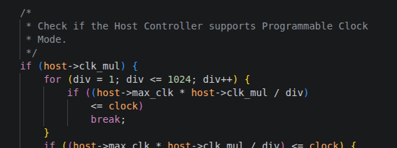
    Div cannot be changed in software.It is calculated using the below logic. In your case for clock =150Hz which you have given the div value is  div=2 as ((200Mhz)/2<=150MHz).

    Can we modify eMMC driver code to hard-code 150MHz? If yes, how?

    No , that is not possible, as the hardware will not support it.(the only possible actual clock values are 200Mhz(200/1), 100Mhz(200/2) , (200/4), 200/6 ...)

    Best Regards

    Gokul Praveen