


Part Number: AM62A7
Other Parts Discussed in Thread: SYSCONFIG, AM62A3-Q1
How to configure clock source for DCC Safety Diagnostic ?

The Dual Clock Comparator (DCC) is a hardware diagnostic module used to determine the accuracy of a clock signal during application runtime. It measures the frequency of a selectable Test Clock (CLK1) source using a known, reliable Reference Clock (CLK0) source.
The DCC can also be configured to operate in single-shot or continuous mode. In single-shot mode, DCC performs a one-time countdown where DCC stops operation when the counters reach 0. A completion interrupt is raised and the status can be checked. In continuous mode, DCC reloads both counts with the seed value upon completion without error. In case of an error, an ESM error event is raised.
DCC Instance- Multiple instances exist on a single SoC so that several clocks can be monitored simultaneously and independently.
Each DCC Instance has two independent counter paths:
Each DCC instance exposes two clock source selection registers:
Example: DCC0 Input Source Clock Mapping
| DCC0 | DCC_INPUT00_CLK | 0 | 0 | CLK_12M_RC |
The DCC Input Clock Source Mapping can be found in AM62Ax Sitara Processors Technical Reference Manual.
AM62Ax Sitara Processors Technical Reference Manual (Rev. C)
4.15.1.3 DCC Input Source Clock Mapping (AM62A):
| DCC0 | 4-267 |
| DCC1 | 4-268 |
| DCC2 | 4-269 |
| DCC3 | 4-270 |
| DCC4 | 4-271 |
| DCC5 | 4-272 |
| DCC6 | 4-273 |
| MCU_DCC0 | 4-274 |
| MCU_DCC1 | 4-275 |
Open the Clock Tree tool within SysConfig to visually trace a component to its clock source and read the operational frequency.
| DCC0 | 4-267 |
| DCC1 | 4-268 |
| DCC2 | 4-269 |
| DCC3 | 4-270 |
| DCC4 | 4-271 |
| DCC5 | 4-272 |
| DCC6 | 4-273 |
| MCU_DCC0 | 4-274 |
| MCU_DCC1 | 4-275 |
Open the Clock Tree tool within SysConfig to visually trace a component to its clock source and read the operational frequency.

Start the design → Search the component of interest
Example: C7X256V0_C7XV_CORE_0
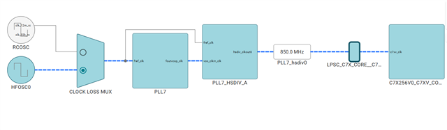
The clock source for C7X256V0_C7XV_CORE_0 is PLL7_hsdiv0 and the frequency reaching C7X256V0_C7XV_CORE_0 is 850 MHz.
→ To find the DCC mapping of the above source clock source i.e PLL7_hsdiv0 refer to the The DCC Input Clock Source Mapping table in AM62Ax Sitara Processors Technical Reference Manual.
The C7X256V0_CLK (or PLL7_hsdiv0 ) clock source is mapped to DCC3 instance → DCC_CLKSRC2_CLK.
CLK0 (reference) ──→ [ Counter 0 ] ──→ counts down from SEED0 ---→ when counter reaches 0, VALID_SEED0 count down starts
CLK1 (test clock) ──→ [ Counter 1 ] ──→ counts down from SEED1 ---→ Counter1 should reach 0 during the time when VALID0 is running, else ESM error is raised
→ How To Configure Clock Source:
SDL_DCC_Config configParams;
configParams.mode = SDL_DCC_MODE_CONTINUOUS; /*DCC Configured in Continuous Mode */
configParams.clk0Src = SDL_DCC_CLK0_SRC_CLOCK0_2; /* Select Input0 to be CLOCK0[2] */
configParams.clk1Src = SDL_DCC_CLK1_SRC_CLOCKSRC2; /* Select Input1 to be CLKSRC2 */
→ To Calculate The Seed Values:
Below functions are defined in the MCU+SDK DCC Example to calculate the Seed Values,
For detailed DCC compute calculations, refer to Continuous Monitor of the PLL Frequency With the DCC App Note.
The SDL DCC seed values calculation is based on DCC Computation Tool for AM263x MCU
→ Configure MCU DCC Instance 0 seed values and clocks:
SDL_DCC_configure(SDL_DCC_INST_MCU_DCC0, &configParams);
→ Enable Error Interrupt for MCU_DCC0:
SDL_DCC_enableIntr(SDL_DCC_INST_MCU_DCC0, SDL_DCC_INTERRUPT_ERR);
→ For Single-Shot Mode, Enable Done Interrupt:
SDL_DCC_enableIntr(SDL_DCC_INST_MCU_DCC0, SDL_DCC_INTERRUPT_DONE);
→ Enable DCC Instance:
SDL_DCC_enable(SDL_DCC_INST_MCU_DCC0);
