AM62P-Q1: AM62P - DPI output

Part Number: AM62P-Q1
Other Parts Discussed in Thread: AM62P

Hi TI Experts,

In our IVI system project, we are planning to interface the DPI output of the AM62P SoC with the UB921 serializer. From the AM62P SoC, we are planning to route the VOUT data signals as shown in the figure below.

Could you please review this implementation and confirm whether it is correct?

As per our understanding:

  • D0–D7 correspond to the Blue data bits.
  • D8–D15 correspond to the Green data bits.
  • D16–D23 correspond to the Red data bits.

We would like to clarify whether the VOUT pins (VOUT00–VOUT23) on the AM62P SoC are dedicated to specific color components or if their mapping can be configured through software/drivers.

Are there any concerns or recommendations regarding the implementation shown below?

Any feedback would be highly appreciated.

SOC-DPI-FPD.jpg


Regards,

Adarsh.

  • Hello Adarsh,

    Thank you for your query !

    What are the MIPI DPI 2.0 RGB formats that you like to use as input to the DS90UB921 serializer ?  

    • D0–D7 correspond to the Blue data bits.
    • D8–D15 correspond to the Green data bits.
    • D16–D23 correspond to the Red data bits.

    Referring the AM62Px TRM / Chapter, Display Subsystem and Peripherals / Section, DSS Environment / Section, DSS Parallel Interface / Section, Pixel Data Formats:

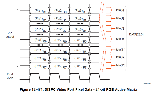
    I think that what you state will be true, if BGR888 mapping is selected for a 24-bit pixel output to an active matrix display (8-bit per color coding). In this case each of the 3 different pixels is encoded in a separate byte of the 24-bit VP1/VP2 video port starting from the LSB to MSB and output on the VOUT0_DATA[23:0] corresponding SoC level pins.

    Assuming VP1 output, to configure 24-bit bus data length you should set DSS_VP1_CONTROL[10-8] DATALINES with the respective value, 0x3. 

    I think that the appropriate format (with each pixel mapped in exactly one byte and LSB to MSB order B-G-R) which can be selected to match your schematic is highlighted in the below table of the Section, DISPC Functional Description / Section, DISPC Pixel Data Formats from the AM62Px TRM.

     The section describes that the format is selected in the DSS_VID_ATTRIBUTES[6:1] FORMAT bitfield. You should set it to 0xC:BGR24-888. 

    We would like to clarify whether the VOUT pins (VOUT00–VOUT23) on the AM62P SoC are dedicated to specific color components or if their mapping can be configured through software/drivers.

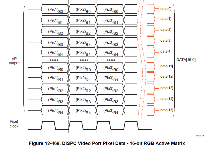
    I think that the DSS hardware allows through the different supported pixel data formats listed above NOT only different pixel ordering (BGR or RGB) but also possibility to have  bits of different pixels (when used bpp < 8 ) within the same VP1 or VP2 byte. I think the mapping is entriely controlled at DSS level and  the DSS0 or DSS1 VP1 / VP2 ports bytes are multiplexed without any SoC level bit re-ordering to the AM62Px VOUT0_DATA[23:0] pins.

    An example is: BGR16-565 in which case I would expect that VOUT0_DATA[16:23] remain unused, because the 3 pixels are fit in exactly 2 bytes:

    Please allow me some time to discuss with our expert and confirm in 1 or 2 days.

    Looking forward to your feedback !

    Best Regards,

    Anastas Yordanov

  • Hi Adarsh,

    I have the confirmation from our DSS hardware expert that the suggested mapping of the VOUT interface to the serializer looks correct. Also, it is possible to reconfigure the color assignment from the default D0-D7 for BLUE, D8-15 for GREEN, D16-D23 for RED. The recommended approach for changing this assignment is via software. If you use Linux SDK (I assume, because your product is IVI), the software changes would need to be done from the device tree source configuration of the SoC.

    I hope this answers your questions ?

    Thanks

    Best Regards,

    Anastas Yordanov