TDA4VEN-Q1: oLDI transmission waveform

Part Number: TDA4VEN-Q1

Hi

I used oLDI IF and captured communication waveforms under the following two conditions:  
A) 1920x1080p, 30fps, RGB888  
B) 1920x1080p, 60fps, RGB888  

As a result, differences were observed in the signal amplitude and common-mode voltage (offset voltage). Especially under the 60fps condition, the common-mode voltage significantly dropped, appearing to be below the general standard (1.2V).  

- What do you think could be causing these kinds of waveforms?  
For reference, the signal wiring is designed with Zdiff = 100 ohms.  
- When we tried video communication at 60fps, the downstream monitor did not display any image. Could these waveforms be the reason?
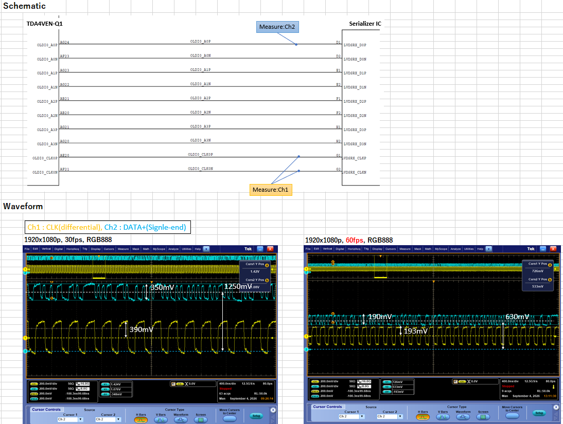
 

image.png

  • Hello Yamamoto-san,

    We moved this thread from Logic forum to Processors forum.

    Best regards,

    -Shibata

  • Hi Yamamoto-san,

    The clk and data lines need to have 100ohm differential termination.

    could you also measure the SERDES 0.8V rail during the second case? Is it room temp and nominal voltage being set? 

  • Hi Yamamoto-san,

    Are you able to measure the common mode voltage of the clock as well to see if the voltage shift is only affecting the data signal?

    Would you also be able to provide any information about the Serializer IC you are using? 

    Best Regards,

    Miles

  • Hi Yamamoto-san,

    Also, please confirm the termination scheme is the same for both fps cases. Please ensure MAIN_CTRL_MMR_CFG0_OLDI1_DAT0_IO_CTRL and MAIN_CTRL_MMR_CFG0_OLDI2_DAT0_IO_CTRL registers remain unchanged for both 30fps and 60fps.

    Best regards,

    Luis Parga

  • The OLDI0_DAT0_IO_CTRL and OLDI0_CLK0_IO_CTRL are hidden in the public register sheet.

    Please use 0x108600 (DAT0) and 0x108610 (CLK) and read out the register.

    Also, are your scope setting to high impedance or 50ohm which could halve the amplitude. 

  • Hi.

    The CLK and DATA are terminated with 100Ω, and that's the same for both 30fps mode and 60fps mode.

    Also, oscilloscope is set to high impedance.

    The temperature is at room temperature, and the voltage is set to the nominal value.

    I'll try measuring the common-mode voltage of the clock, so please wait.

    The serializer we're using is a Sony GVIF IC.

    Thank you. I'll check the OLDI0_DAT0_IO_CTRL and OLDI0_CLK0_IO_CTRL registers.

    Could you tell me the expected values?

    Regards,

    Yamamoto

  • Thank you for the confirmation of the conditions.

    If possible, please measure the SERDES voltage and current value in both the cases( 30/60fps); 

    There is RX term enable available on the IO_CTRL as well as control over the term value and the TX drive strength if possible can be increased through them. Would like to read the value and then try to see if changing them make change to the waveform. 

  • Hi Yamamoto-san,

    The expected value for these 2 registers is 0xC1043008. Please let us know if this is what you see on your end.

    Best regards,

    Luis Parga

  • Hi Rao-san,

    Regarding the voltage and current values of the SERDES, specifically, for which signal (e.g., Data0 Pos), which voltage (e.g., Vcommon, Vdiff), and which current should we measure?

    Is the waveform image I attached at the beginning of the inquiry insufficient?

    Regards,

    Yamamoto.

  • Hi Parga-san,

    Please wait a moment while I check.

    Just for reference, could you tell me what kind of register is this, and what does the expected value mean?

    Regards,

    Yamamoto.

  • Yamamoto-san,

    This is the VDDA_SERDES0p85V rail voltage and current and not the OLDI Data/CLK voltage I requested.

    Are you running a single link or dual link with both CLK0/CLK1 and Data0/Dat1 active at the same time? Are the CLK1 read out and at the expected voltage?  

  • Hi Yamamoto-san,

    This is a MAIN_CTRL_MMR register. The 0xC1043008 value means that the default LVDS TX drive current of 3.2mA is being used, the LVDS RX is deactivated, and the LVDS RX termination (internal SoC termination) is also deactivated.

    Best regards,

    Luis Parga

  • Rao-san,

    VDDA_SERDES0p85V current requires circuit board modification, so currently, it is difficult.
    The voltage is 0.85V.

    Also, since oLDI uses single-link, CLK1P/N is not used.

    Regards,

    Yamamoto

  • Thank you.

    Were you able to get the register readout?

  • Rao-san,

    Sorry for the slow response.
    We need to make a software fix for the SoC, but we haven’t been able to start yet due to prioritizing other issues.
    We’ll monitor the registers aiming for early next week.

    Regards,

  • Hi Yamamoto-san,

    Thank you for the update. When you read the registers early next week would you also be able to measure the common mode voltage of the data signal with the new software? If it is still half of the expected voltage, can you measure the common mode voltage of the clock as well? Would you also measure the frequency of the clock signal if the problem persists after the update?

    Regards,

    Miles

  • Miles-san,

    Sorry for being slow with measuring the waveforms.

    I’m prioritizing dealing with the MIPI-CSI2 communication issues, so I haven’t been able to get to it yet.

    I’ll measure the waveforms as soon as the MIPI-CSI2 issues settle down, so please wait.

    Regards,