This thread has been locked.

If you have a related question, please click the "Ask a related question" button in the top right corner. The newly created question will be automatically linked to this question.

VPFE problem using Image Tuning Tool

Hello all,

         i use the  Image Tuning Tool to tune image, when i tune the Black Clamp (DC offset)  i get a problem:


        As the UserGuide describes and my consideration, i go through the follow step :

      1. turn off AE and AWB.

       2.turn off sensor digital gain

       3.set ISIF DC offset =0 and ISIF Gain =512(1.0x) in Image Tuning Tool.

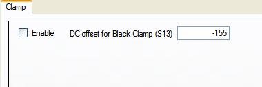
       4.disable Black Clamp in Image Tuning Tool.

       5.set black clamp DC offset  = 0( in Image Tuning Tool)

       6. disable LDC

       7.turn off Iris (no light into sensor).

       Using the Image Tuning Tool to capture a *.rawTI data, and then using the Image Tuning tool to generate the DC Offset,


       the Problem is i find i get the wrong result, the image appears i have put a wrong DC offset value .

       i am Tuning the DM368, with the Image Tuning Tool Version 2.1 and IPNC2.6.   Any input is appreciate!

  • Hi 

    when you complete DC offset tuing in ITT, the DC offset value will be displayed in the GUI as below. What is the DC offset value that you got for your setup?. Also Could you please check the value written in Register (ISIF_CLDCOFST) is same as the value you got from the GUI.

    I

    BTW, Are you using the Lite version ITT or Full version ITT?

    Regards,

    Kumar.

  • Hi Kumar,

           Thank you very much for your reply.

           I have checked that I am using the Full version ITT, 

    " when you complete DC offset tuing in ITT, the DC offset value will be displayed in the GUI as below. What is the DC offset value that you got for your setup?."  \

    The DC offset value I got from my setup is -50, and I use the command "./regrw.out 1c710b0 16 -c 1"  I read the Register ISIF_CLDCOFST value back , and it shows 0x01c710b0 : 00001fce (exactly -50) ,and i also sent value 3 to the Register ISIF_CLDCOFST  , and using the same method , i get the register value 3. and it looks all ok.


    Are there Any things I omit to do ?  Thanks for any comment!


  • Hi,

    Are you saying that your image looks ok with  ISIF_CLDCOFST=3 ?

    Can you capture a RAW with ISIF_CLDCOFST=0 and and one with ISIF_CLDCOFST = -53 and share the same with us. Also share a snap of final image from the IPNC (YUV or the snap from IE)

    Regards,

    Kumar.

  • HI, Kumar !

        Thank you for caring my problem.

        The image looks lack of dynamic range(in histogram, it should be in a narrow range, looks like some fog in front of the image) when applying the parameter ISIF_CLDCOFST=3. and when applying the -167(default value) it looks ok.  In above post , I mean  the Tool can send the right things to IPNC (as I can read the Register back using the regrw.out tool ,the Register value I have read back is the same as what I had input on the Image Tuning Tool).

       Are you still need the Raw data ?

       Regards.

       WqPang.


  • WqPang,

    The RAW images will help me in figuring out the reason for ITT calculation of DC offset as -50. So, please share the RAW images if possible.

    Regards,

    Kumar

  • Hi, Kumar !

          Thanks again for your kind help!


          Below  is the Raw data (I capture it when tuning black clamp, with the iris closed):

    Repeat the step of tuning black clamp, and close the Iris ,

    1.use the vlc to capture the image:

    7485.vlc.tar.gz

    2.use the Imag Tuning Tool to capture the image

         5635.ITT.tar.gz

    3.use the IE to captue image

    5516.IE.tar.gz

    4. the normal image (with iris open):

    5270.IE_normal_image.tar.gz


  • Hi,

    Is there any chance the RAW data that you are storing to DDR is 10 bit. Can you check the CCDW value in "ISIF_MODESET". I am guessing that the RAW data stored is 10 bit, which is 4 time is lesser than the data going to IPIPE.

     We can also confirm this by capturing a RAW image with high exposure and check the max value in raw file.

    Regards,

    Kumar

  • Hi, Kumar !

         Thank you very much for you kind help, you have hit the right point of the problem!

         When I read back the MODESET, I indeed found the image data right shift 2 bit when it was written to DDR2. Now the Black Clamp DC offset works OK!

        "We can also confirm this by capturing a RAW image with high exposure and check the max value in raw file."

          As you mention above, when I want to check the Black clamp DC offset , I can let the exposure to 1/25 with iris completely close, then capture a raw data, then check the max value in raw file, but  is it  possible that there are hot pixels or bad pixels in  image sensor ?  If so , how can I determine the Black Clamp DC offset ?


         Another question: When image data enter into the DM368, they  substract the  Black Clamp DC offset  value , and when the IPNC send a digital or analog  gain to  the image sensor ,should  the DM368 subtract the Black Clamp DC offset  value with the same  gain ?  It means that   ( image_data x Dgain1/Again1 - DC_offset x Dgain1/Again1 ) ?


          Regards,

          WqPang.


  • WqPang,

    Since we know the reason for wrong calculation is right shift value in MODESET, we don't need to do the other experiment (capturing RAW with high exposure).

    Regrading your question about multiplying the DC offset with Agian/ Dagain, this is not required. Normally the sensor offset will not depend on the Again or the dgain applied inside the sensor. You can also confirm this by doing the DC offset calculation experiment with different analoggains.

    Regards,

    Kumar.

  • Hi ,Kumar !

           Thanks very much for your reply !  I have finished black clamp dc offset tuning. I will continue and start the color tuning !


       Regards,

     WqPang.