This thread has been locked.

If you have a related question, please click the "Ask a related question" button in the top right corner. The newly created question will be automatically linked to this question.

I2C communication through stream API to multiple slaves

Hi,
I have trouble using the I2C driver through the stream API. I use the I2C driver in pspdrivers_02_20_02_01.

Congifuration:
-Polled
-Master
-7-bits adress
-200 khz
-DMA disabled

If I do to consecutive stream_write to the same I2C slave everything works fine, but If do one stream_write to one I2C slave and one stream_write to another I2C slave the second failes. The return code from stream_write is 0 and Error_getCode(&eb) returns 0.

Is it only possible to communicate with one I2C slave with the I2C driver through the stream API?

Best regards,
Jonas
  • Hi Jonas,

    We have not tested this, but it should be working.We will try to implement this at our end, and get back to you soon.

    BTW, have you tried consecutive transfers on both the slaves seperately?.

    Best Regards,

    Raghavendra

  • Hi,

    I just managed to send I2C messages to two slaves using the stream API. The problem was that the ownAddr is configured to 0x10h in i2c.xdc and I did not configure that explicitly in my cfg file. 0x10h was the address of my other I2C slave. That was why the driver complained.

    Now I have two other problems though.

    1. If I do two consecutive stream_write (one to each slave), the second stream_write never returns. I have to put a Task_sleep between the two Stream_write. Why is this?

    2. I have problems using stream_read on I2C. Can you please provide me an example on this. The I2C examples in the psp package does not have a functioning read example.

    If I do as in my example below it works fine the first time. If I execute the code below twice the stream_write will fail the second time. The following error is reported:

    [CortxA8] ti.psp.i2c.I2c: line 2560: E_timeOut: Error in Timeout
    xdc.runtime.Error.raise: terminating execution


    /*************************************/
    i2cParams.slaveAddr = (0x10u);
    i2cParams.buffer = pBuffer;
    i2cParams.bufLen = length;
    i2cParams.flags = I2c_START | I2c_MASTER | I2c_WRITE | flags;
     
    /* Prepare I2C slave for read */
    size = Stream_write(inst->writeHandle,&i2cParams,(SizeT)i2cParams.bufLen,
    BIOS_WAIT_FOREVER,&eb);
    if ((TRUE == Error_check(&eb)) && (i2cParams.bufLen != size))
    {
    printf("I2c Write: Data Write Failed: %d\n",Error_getCode(&eb));
    retval = FALSE;
    }
    i2cParams.slaveAddr = (0x10u);
    i2cParams.buffer = pBuffer;
    i2cParams.bufLen = length;
    i2cParams.flags = I2c_RESTART | I2c_READ | I2c_MASTER | I2c_IGNORE_BUS_BUSY | I2c_STOP;
       
    /* Read data from camera */
    size = Stream_read(inst->readHandle,&i2cParams,(SizeT)i2cParams.bufLen,
    BIOS_WAIT_FOREVER, &eb);

    if ((TRUE == Error_check(&eb)) && (i2cParams.bufLen != size))
    {
    printf("I2c Write: Data Read Failed: %d\n",Error_getCode(&eb));
    retval = FALSE;
    }

    Do you have any ideas why this happens?

    BR,

    Jonas

  • Hi Jonas,

    Please find the I2C sample application attached.

    It is modified to write both to the I/O expander and the Codec register(both read/write). The sample application binaries are also available in the zip file which can be run on the C674x DSP of DM8148 EVM. You will be able to see the LED’s blinking(verifies writing to IO expander) and the Codec register value(that are written using Stream_write()) printed on the CCS console(verifies writing/reading the Codec register). 

     The I2C is configured to work in polled mode, 7 bit addressing, 200KHz bus frequency.

    Please go through the configurations done in the sample application, and also Stream API's implementation for read/write operation.


    Let me know the results. Hope this helps..

    Best Regards,

    Raghavendra

    i2c.zip
  • Hi Raghavendra, 

    Thank you for the sample files!

    I have tested using the same stream methods as in the sample files and I still get the behavior as described in my previous post. I get the following error on the first stream_write after the stream_read.

    [CortxA8] ti.psp.i2c.I2c: line 2560: E_timeOut: Error in Timeout

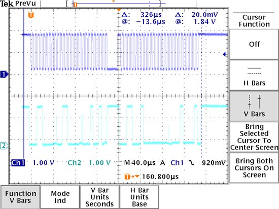
    I have analyzed the first stream_read closer (the read that seem to work without errors) and have found something "interesting". The first stream_write and stream_read combination generetes a valid I2C sequence (verified on an oscilloscope). The problem is that the data received in stream_read does not correspond to the data seen on the oscilloscope. According to the oscilloscope the first byte is 0x00 and the second is 0x10. The data recevied from stream_read is 0x00 and 0x91.

    The return value from stream_read is 2 (which is expected).

    After this when I try to read another register from the I2C slave by starting with a stream_write to set the address in the slave, the timeout error described above occurs.

    This is driving me insane. Could you please test your sample code on the A8 with the same psp driver version?  We have the following driver package: av_bios_sdk_00_04_00_00

    Thanks in advance!

    Best regards,

    Jonas

  • Hi again,

    As it is now I can not debug the ti.psp.I2c driver to see what happens. Is there an easy way to do so? I guess I have to build the driver my self to get all the debug info?

    BR,

    Jonas

  • Hi Jonas,

    I tried the sample files on the ARM too. The application runs successfully without any errors.

    Jonas Karlsson said:
    [CortxA8] ti.psp.i2c.I2c: line 2560: E_timeOut: Error in Timeout

    I believe, this is something to do with the slave itself. Did you run/try the sample files(shared earlier)directly, or you modified it? Are you using a custom board or DM8148 EVM?

    Jonas Karlsson said:

    As it is now I can not debug the ti.psp.I2c driver to see what happens. Is there an easy way to do so? I guess I have to build the driver my self to get all the debug info?

    You should be able to place breakpoints in the driver, like at - i2cMdSubmitChan(), i2cMdCreateChan(), etc.. functions in I2c.c file to debug.

    Thanks and Regards,

    Raghavendra

  • Hi Raghavendra,

    Thank you for the effort of trying to reproduce the issues I've seen.

    I had to modify the your example code slightly. We read 16 bits instead of 8 and do not use DMA. Here is the test code:

    /*********Debug code*************/
    {
    I2C_instance inst;
    bool retVal;
    U16 reg;
    I2c_DataParam dataBuffer;
    #define I2C_SLAVE_ADDR2 (0x18u) /* i2c address of Aic31 Codec */
    Error_Block eb;
    UInt32 size = 0;
    Stream_Params streamparams;
    I2c_ChanParams chanParams;
    int i;

    /* Monitor OE as an input, BoB tool is master of this line */
    GPIO_enableInput(GPIO_CAM_OEn);
    /* Reset is controlled by the VP */
    GPIO_setLow(GPIO_CAM_RESETn);
    GPIO_enableOutput(GPIO_CAM_RESETn);
    /* Trigger #0 is controlled by the VP */
    GPIO_setLow(GPIO_CAM_TRIGGER);
    GPIO_enableOutput(GPIO_CAM_TRIGGER);
    /* Address pin is controlled by the VP */
    GPIO_setHigh(GPIO_CAM1_ADDR);
    GPIO_enableOutput(GPIO_CAM1_ADDR);
    /* Stereo frame pin is controlled by the VP */
    GPIO_setLow(GPIO_STEREO_FRAME);
    GPIO_enableOutput(GPIO_STEREO_FRAME);
    GPIO_setHigh(GPIO_CAM1_ADDR);
    /* Configure pin control */
    APTA_boardspecificInit();

    I2C_boardSpecificInit();

    /* Reset camera */
    GPIO_setLow(GPIO_CAM_RESETn);
    for (i=0; i<0x00FFFFFF; i++) {} //Dummy delay
    GPIO_setHigh(GPIO_CAM_RESETn);
    for (i=0; i<0x00FFFFFF; i++) {} //Dummy delay


    /* Initialize the Error Block */
    Error_init(&eb);

    /* Update the channel parameters */
    chanParams.masterOrSlave = I2c_CommMode_MASTER;

    /* Initialize channel attributes. */
    Stream_Params_init(&streamparams);

    /* Assign the channel parameters */
    streamparams.chanParams = (UArg)&chanParams;

    printf("I2C : Start of I2C sample application. \n");

    /* Create the I2C Channels for the TX and RX communication */
    i2cWriteHandle = Stream_create("/i2c0",DriverTypes_OUTPUT,&streamparams,&eb);
    i2cReadHandle = Stream_create("/i2c0",DriverTypes_INPUT,&streamparams,&eb);

    if ((NULL == i2cWriteHandle) || (NULL == i2cReadHandle))
    {
    printf("I2C : I2C Handle Create Failed.\n");
    }

    for (i=0; i<2; i++)
    {

    reg = 0x3012u;

    rBuffer[0] = ((U8 *)&reg)[1];
    rBuffer[1] = ((U8 *)&reg)[0];

    /* Prepare the data to be written to the audio codec */
    dataBuffer.slaveAddr = I2C_SLAVE_ADDR2;
    dataBuffer.buffer = &rBuffer[0];
    dataBuffer.bufLen = 2u;
    dataBuffer.flags = I2c_WRITE | I2c_MASTER | I2c_START;

    size = Stream_write(i2cWriteHandle,&dataBuffer,(SizeT)dataBuffer.bufLen,BIOS_WAIT_FOREVER,&eb);

    if ((TRUE == Error_check(&eb)) && (dataBuffer.bufLen != size))
    {
    printf( "I2C Expander configuration failed : %d!",Error_getCode(&eb));
    }
    rBuffer[0] = 0x00; // reset the buffer
    /* Prepare the data to be written to the audio codec */
    dataBuffer.slaveAddr = I2C_SLAVE_ADDR2;
    dataBuffer.buffer = &rBuffer[0];// read value of the register resides here
    dataBuffer.bufLen = 2u;
    dataBuffer.flags = I2c_READ
    | I2c_MASTER
    | I2c_STOP
    | I2c_RESTART;

     size = Stream_read(i2cReadHandle,&dataBuffer,(SizeT)dataBuffer.bufLen,BIOS_WAIT_FOREVER,&eb);

    if ((TRUE == Error_check(&eb)) && (dataBuffer.bufLen != size))
    {
    printf( "I2C Expander configuration failed : %d!",Error_getCode(&eb));
    }
    else
    {
    printf("read value = 0x%x, 0x%x\r\n", rBuffer[0], rBuffer[1]);
    }
    }
    }
    /***************************************************/
    Here is the section regarding I2C in the config file:
    /*************************** Configure the I2C module ***********************************/
    /* Configure the I2c module */
    I2c.edmaEnable = false;

    var i2cPrms = new I2c.Params();
    i2cPrms.instNum = 0;
    i2cPrms.addressing = false;
    i2cPrms.opMode = I2c.OpMode_POLLED;
    /* i2cPrms.opMode = I2c.OpMode_INTERRUPT; */
    i2cPrms.hwiNumber = 8;
    /*i2cPrms.busFreq = 400000; */
    i2cPrms.busFreq = 200000;
    i2cPrms.ownAddr = 0x30;
    i2cPrms.prcmHandle = null;

    var i2c0 = I2c.create(i2cPrms);
    DriverTable.addMeta("/i2c0", i2c0);
    /******************************************************/

    This code generates the following output on stdout:
    [CortxA8] I2C : Start of I2C sample application. 
    [CortxA8] read value = 0x0, 0x91
    [CortxA8] ti.psp.i2c.I2c: line 2560: E_timeOut: Error in Timeout
    xdc.runtime.Error.raise: terminating execution

    The timeout error comes from the Stream_write in the second lap of the for-loop. 
    The oscilloscope view for the successful read can be seen below. The value from Stream_write (0x00 and 0x91) is not correct according to the oscilloscope view.


    How can I place breakpoints in the driver? How do I get code composer to map the I2c.c file to the debug symbols in the driver?
    Best Regards,
    Jonas


  • Hi Jonas,

    Jonas Karlsson said:
    The timeout error comes from the Stream_write in the second lap of the for-loop.

    So for the first time, the read and the consecutive write succeeds. Entering the next sequence(loop 2nd time) the write fails. Is my understanding correct? 

    Jonas Karlsson said:
    How can I place breakpoints in the driver? How do I get code composer to map the I2c.c file to the debug symbols in the driver?

    Copy the name of the function(where you intend to place the breakpoint)and paste it in the disassembly and then place the breakpoint in the disassembly itself. When run, the breakpoint is hit and then locate the source file(i2c.c) in the CCS. Then, you should be able to proceed debugging. Try placing the breakpoint in functions - "i2cIntrHandlerErr"(check if there are any errors), "i2cCommonIntrProc", "i2cCompleteIO", etc. Also check the state of I2C(Register status) when error occurs.

    Hope this helps..

    Meanwhile, I shall check the configurations you mentioned.

    Best Regards,

    Raghavendra

  • Hi Raghavendra,

    Yes, the first loop succeeds with no errors, but with unexpexted data (compared to oscilloscope view). Yes, the write for the second loop fails.

    I will try to debug as you described.

    Best Regards,

    Jonas

  • Hi Jonas,

    Actually, the write does not fail. In fact its because of the read the I2C timeout occurs(Stream_read might return, but it may not complete successfully). If you refer the AIC31 Codec Figure 18 explains i2C read. Since the codec register itself is 8 bit, its not possible to read 16 bit data. Refer the sample application shared earlier which has the implementation for performing read/write with the Codec. 

    Step A: Write the address of the register to be read(Note: The I2C stop should not be issued)

    Step B: Issue I2C restart.

    Step C: Read the value of the register. 

    Hope this helps..

    Best Regards,

    Raghavendra

  • Hi again,

    I am using a custom boards and the I2C slave I'm communicating with is a camera. It has 16-bits registers.That's why I read 16-bits. It is the same camera I use together with my PG1.0 based boards, so the camera is ok. You can also see on the oscilloscope that the pulse sequence is valid.

    I have not been successful stepping source code in the driver, but I have been setting breakpoints in disassembly to see what happens. The interesting thing is that if I set a breakpoint in i2cCommonIntrProc() and then continue executing the Stream_read returns the correct value (0x00, 0x10 as seen in oscilloscope view). After that the next Stream_write in the next lap of the loop is ok.

    Could there be somekind of race condition in the driver?

    Best regards,

    Jonas

  • Hi Raghavendra,

    I forgot a question. Is the I2C driver tested at all regarding Stream_read with multiple bytes. As in our case 16-bit reads?

    Best regards,

    Jonas

  • Hi Jonas,

    It looks like a bug in the I2C driver. To verify/confirm, we will need to do an experiment. Since I do not have the setup, I request you to try this at your end and get back to me. Place the following line in the i2csample.cfg file. 

    i2cPrms.rxThreshold   = 2;

    Build the sample application and test it. Let us know the results..

    Best Regards,

    Raghavendra

  • Hi Raghavendra,

    I did a quick test and will investigate deeper tomorrow, but it seems to work with your experiment. Let me get back to you tomorrow.

    Best regards,

    Jonas

  • Hi Raghavendra,

    I have done some more testing this morning and it seems to work without any errors with your workaround.

    Can I use your workaround if I only read 16-bits registers or do I have to wait for a new updated release of the psp-package?

    Thank you for the effort!

    Best regards,

    Jonas

  • Hi Jonas,

    I shall provide a fix to this issue, please check this at you end and let me know the results. Depending on this, I shall proceed and raise an IR.

    Modify Line 2117 under function i2cCommonIntrProc(..) of I2c.c file as shown below - 

            /******************* Recevier full interrupts**************************/
    if (CSL_I2C_IRQSTATUS_RRDY_MASK ==
    (intStatus & CSL_I2C_IRQSTATUS_RRDY_MASK))
    {
    /* In master mode if the buffer is not a integral multiple of *
    * threshold, then we need to manually check the residual *
    * value and transfer the same */
    if ((I2c_CommMode_MASTER == chanHandle->masterOrSlave) &&
    (chanHandle->currBufferLen <= instHandle->rxThreshold))
    {
    /* update the threshold to the residual value so that the *
    * remaining value is transferred.in SLAVE mode it is not *
    * required as the threshold will already be 1 */
    threshold = chanHandle->currBufferLen;
    }
    else
    {
    /* This is a normal transfer.Hence program the threshold count*
    * of data */
    threshold = instHandle->rxThreshold;
    }
    
    
    Let me know..
    
    
    Best Regards,
    Raghavendra
  • Hi,

    How do I rebuild the library?

    BR;

    Jonas

  • Hi Jonas,

    Please refer section 1.3.3(Building the BIOS PSP Driver Modules - step 2) of the BIOS PSP Userguide placed in the top level docs folder of the psp package.

    Before building, please make sure you go through the following sections too - 1.2, 1.3 of the Userguide.

    Hope this helps..

    Best Regards,

    Raghavendra

  • Hi Raghavendra,

    I have rebuilt the driver and removed the rxThreshold setting from the cfg file. The cameras start up as expected, so it seems like you have the solution there.

    Best Regards,

    Jonas