This thread has been locked.

If you have a related question, please click the "Ask a related question" button in the top right corner. The newly created question will be automatically linked to this question.

question about tms320c6670 spi

Hi all,

I'm currently working on writing driver for 6670 spi. There are 2 flashes connecting to dsp. One is directly connecting to dsp. The other is connecting to dsp via cpld.

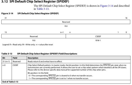
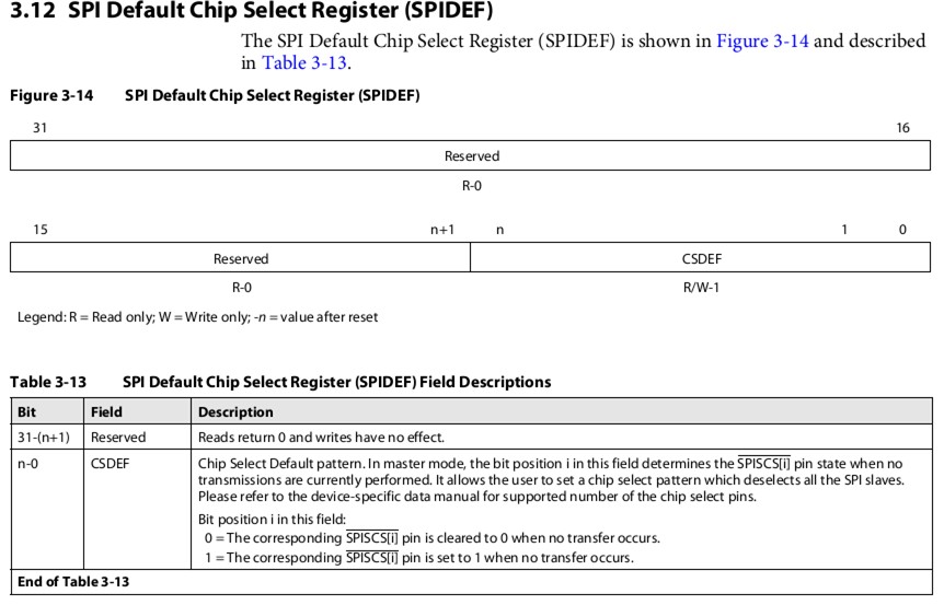
The problem is all about the latter flash. When I initialiaze spi module, after I set the default state for cs pin, which is, the cs pin is in high state when there is no data

on the spi bus, the cs pin for the latter flash transferred to low state. And the state didn't go back to high state. Only did the cs pin state go back to high, the instruction

for flash can be written into it. So I couldn't write or read the flash. Could you tell me why is the cs state is always in low state? Please help.

Thank you

Best regards,

Nick

  • Nick,

    There are several registers related to the SPI chip select pins (/SPISCS[n]). I think you already select the Master mode (bit[1:0]=3 in SPIGCR1) and make /SPISCS[0]&[1] to be functional pins (bits[1:0]=3 in SPIPC0).

    One thing to mention is that the CSDEF field in SPIDEF needs to be updated in the SPI user's guide that there are N bits assigned to  /SPISCS[n] pins, which means bit[1] in SPIDEF is for /SPISCS[1] and bit[0] is for /SPISCS[0]. So you should set both bits[1:0] for the default chip select pattern,

    And there are also some updates in SPIDAT1 register as follows:

    Please pay attention to CSHOLD description that if it is set to 1, the /SPISCS[n] values will be continued as CSNR values at the end of transactions (not as defined in CSDEF).

    Those changes will be updated in the next release of SPI user's guide soon. Hope it helps.

    Sincerely,

    Steven

  • Hi Steven,

    Thank you for your quick answer. It helps me a lot. And I know the SPI more better.

    But I can't see it clearly. Could you give me the latest release version of the SPI document?

    Thanks

    Best regards,

    Nick

  • Nick,

    The SPI user guide is still being revised and not published yet. I attached the JPG format files for those two registers and it should be clear. Please take a look if anything is helpful.

    Sincerely,

    Steven

  • In the description of the CSDEF bits in the SPIDEF register, does '0' imply the chip select output pin is active (low voltage) or does it imply the chip select output pin is inactive (high voltage)?