This thread has been locked.

If you have a related question, please click the "Ask a related question" button in the top right corner. The newly created question will be automatically linked to this question.

ADS1298 RDATAC interrupt

Other Parts Discussed in Thread: ADS1298, SPRC133

Hi all,

I am trying to take continuous data from ADS1298, I successfully write and read to Status registers of ADS1298 via SPI. Now I am trying to get three package data (each have 9 frames with 24-bit word length, means one status and 8 channel data)  and store the data into a register.

In ECG_NonBios source code there is an interrupt routine int1_isr and C5515 is interrupted after a low signal (DRDY from ADS1298) come to INT1. However I cannot read anything, I put a printf command inside ISR but there is nothing printed on the console. Below is my main function with interrupt routine, they are all in a .c file. I am new to this interrupt issue, if you can advice any source I will appreciate. My development platform is EVM5515 and code CCS Version: 4.1.0.02002 (that is coming with the EVM).

Thank you all in advance.

***.

 void main(void)

{
AllInit();

spi_init();

asm("\tBIT (ST1, #ST1_INTM) = #0"); /*Enable GLobal Int.Mask*/
//
/* Start the Timer0*/
CSL_TIM_0_REGS->TCR = CSL_TIM_0_REGS->TCR | 0x0001;
//
// /*Enable INT1 interrupt */
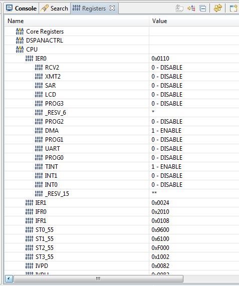
CSL_CPU_REGS->IER0 = CSL_CPU_REGS->IER0 | 0x1008;
}

interrupt void int1_isr()
{

Uint32 SPIBuf[MAXCHAN+2] = {0}; /* SPI Rx Buffer*/
Uint32 ECGDataSample[MAXCHAN]={0};
Uint16 fLen = 0; /* No. words to be read*/
Uint16 wLen = 0;
Uint8 col = 0;

static Int16 LeadAray[8] = {2,3,8,4,5,6,7,1}; // PG 2.0

/* Read data- continuous mode */
fLen = 9;
wLen = 24;

if(even_flag==8)
CSL_CPU_REGS->IER0 = 0x0000;

/*Reading data from ADS1298 */
LLC_SPI_WordLengthRead_v1(SPIBuf,wLen,fLen);
even_flag++;

for ( col =0; col < MAXCHAN; col++)
{
ECGDataSample[col] = SPIBuf[LeadAray[col]];
ECGDataSample[col] = ECGDataSample[col] >> 4;
spiReadBuff[(9*even_flag)+col] = ECGDataSample[col];
printf("ECGDataSample: %x \n",ECGDataSample[col]);
}

return;
}
  • There is a confusion about interrupt registers. The first picture below taken from spru433j document and INT1 is shown in IER1 register.

    However the picture below is taken from sprufx5d document and shows that INT1 interrupt is IER0-3rd bit. 

    There is a thread in processor.wiki says that spru433 is the most up to date document (see picture below and visit the link).

    http://processors.wiki.ti.com/index.php/C5000_Chip_Support_Library#Q:_Are_there_any_updates_to_the_CSL_API_reference_guide.3F_.28SPRU433.29

    I am confused among these documents, can you help?

    Regards.

  • ***,

    There are a couple of things to check.

    1. Make sure you are using the correct CSL package. C55XCSL-LOWPOWER, not SPRC133 (for older C55xx chips).

    2. I would go by the sprufx5d document since it is much newer (spru433 is from 2004 and has not been updated for newer chips. C5515 is a newer chip).

    3. There is a very valuable tool in CCS that lets you look at the actual status of each register in the C5515. You can look directly at the status of INT1 to see if your AD1298 is actually bringing the interrupt line low. If you haven't yet discovered this tool (view) you should find it and use it. Here's a snapshot.

    As you can see, INT1 is in IER0.

    I haven't used the external interrupts yet, but I assume they need to be set for positive or negative transition triggering. It not, they may be positive trigger only. You should check this out also.

    I hope this helps. It's sure is a shame that we can't get better tech support from the guys who actually make these chips. What a shame.

    Good luck!

  • Hello MikeH,

    Thank you for your fast response and consideration. I will check the points as soon as possible. I really appreciate your effort, I do not know to handle problems since there is not such much sources about this DSP chip and also ADS1298.

    Best regards.

  • Hi EkremBayraktar,

    I have met with a similar issue, and just wanted to tell you how I solved it. I do not know if it has anything to do with your problem.

    I used to initialise the SPI normally, using CSL commands. But then, after the rest of the initialisation, the SPI settings became corrupt. I noticed this by debuggind, and watching the SPI configuration registers in the watch window. To solve this issue, I did the SPI initialisation as the last thing, so that there is nothing which could corrupt the SPI configuration.

    Also, another useful advice is to put a break point inside the interrupt service routine, just to check that the code is actually entering the interrupt service routine.

    Regards,

    Simon

  • Simon Attard said:

    Hi EkremBayraktar,

    I have met with a similar issue, and just wanted to tell you how I solved it. I do not know if it has anything to do with your problem.

    I used to initialise the SPI normally, using CSL commands. But then, after the rest of the initialisation, the SPI settings became corrupt. I noticed this by debuggind, and watching the SPI configuration registers in the watch window. To solve this issue, I did the SPI initialisation as the last thing, so that there is nothing which could corrupt the SPI configuration.

    Also, another useful advice is to put a break point inside the interrupt service routine, just to check that the code is actually entering the interrupt service routine.

    Regards,

    Simon

    Hi Simon, 

    Thank you for your advice, it is really interesting that SPI initialization should be done at the end, you may be right. I will share my observations as soon as I try this procedure. 

    Yes, I put some breakpoints inside iinterrupt service routine and realized that my code do not enter ISR, but I couldn't realize what is the reason fpr this, yet.

    I again thank you for your consideration,

    Regards,

    ***.