This thread has been locked.

If you have a related question, please click the "Ask a related question" button in the top right corner. The newly created question will be automatically linked to this question.

ADS8332 Timing

Other Parts Discussed in Thread: ADS8332

Hi all,

I've been working on ADC reading part of a project. My ADC is ADS8332 and DSP is L138. I've been working with DSP/BIOS version 5.41.11.38, BIOS PSP v 1.30.00.05 and CCSv5.1. L138 SPI0 pins and CS pin are directly connected to ADC. Convst and EOC pins are connected to L138's GPIO pins.
I want to use ADS8332 in Auto-Trigger, Auto-Channel mode. Then DSP must read ADC result to two buffers (I want to toggle buffers). My way is setting the timer to change sampling freq, timer drives DMA, DMA reads ADC via SPI. (or adjusting SPI clock to change sampling freq). I need to change sampling freq dynamically.
I've been trying to use BIOS PSP spi driver but I couldn't find detailed document about driver. How to use structures/registers? I couldn't change CS timing. I can't control wdelay, etc. I checked doc folder under PSP, technical manual of L138 (still I can't understand all the structures/registers on SPI driver as well).

- I couldn't configure L138 SPI as I wish.

- How can I use timer to drive EDMA (should I hack the PSP SPI driver) ?

- Which way is better to adjust sampling freq, setting timer or SPI timing? (I guess it will not be easy to use SPI with 42 CLK or something like that)


Thanks in advance

Serdar

  • Hi Serdar,

    I suspect this might really be a question for the OMAP guys.  If you are trying to dynamically change the sampling rate, it might be better to try running the ADS8332 device in Manual Trigger mode by reloading the timer period and using that as a CONVST to the ADC.  Not sure if you can fire off the SPI through DMA based on the timer or not, but you might be able to do that through an external interrupt connected to the EOC/INT pin.

    I'll move your post to the OMAP forum and we'll see if the experts there have any guidance for you on configuring the L138 peripherals to accomplish your end goals.

  • Hi Tom,

    Your are right this question turns out a software challenge. After a few hours struggling, I realized that using CONVST pin (Manual Trigger) is only the way to accurate sampling timing and auto-scan mode.

    I faced some problems in auto-trigger mode; sampling timing is not accurate, I get some wrong samples due to read timing problems ( SPI is not sync with EOC signal) and auto-scan mode is useless unless you don't sample at 250Ks or 500Ks. In auto-scan mode with auto-trigger, ADC changes channel with 500K times/second and I think it is not easy to catch right channels. Using channel tag needs much more effort.

    I have to use ADS8332 with manual-trigger, auto-scan mode enabled and internal oscillator. Timer must drive CONVST pin to trigger ADC. After conversion, EOC pin must drive DSP (interrupt to EDMA) and DSP reads ADC via SPI.

    CONVST (GP5_6) and EOC (GP5_7) pins are connected to L138 GPIO pins. How should I configure DSP/BIOS to implement this or do you consider a different way? I need to implement this without CPU load.

    Thanks

    Serdar 

  • Tom,

    I have no answer from OMAP guys. Also I posted a question to BIOS forum but no one answered me. I couldn't find a way to drive CONVST signal without CPU load. How your customers use this adc without FPGA?

    We had two options to choose adc to this proect ADS8332 and AD7689.  AD7689 has no pin like CONVST. It is much easy to configure and read without FPGA.

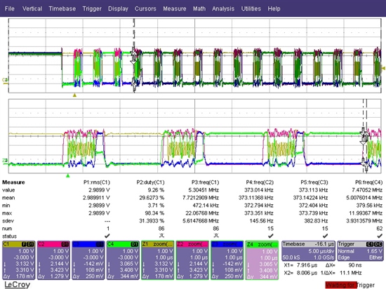
    Then, I shorted ADS8332's CONVST pin with CS pin. I had a problem reading data from adc now. SDO pin goes Z when CS/CONVST is high and then goes high or low. Please check the scope view. What is your opinion? May be a pull-up resistor can solve this issue.

    Thanks

    C1: sclk    C2: EOC   C3: CS/CONVST  C4: SDO