


Hi!
I’m currently starting to debug a custom board, with 3 TMS320C5502 (clock at 27Mhz) on it. Those 3 DSP has their GPIO connected together (so each GPIOx connected together). Apparently (still trying to figure out exactly how to program the 3 DSP), only one processor is running while the two others are in reset. So only one processor is trying to put value on the GPIO port.
So right now, I can load some program on one DSP, and I made some test. The first test I’m trying to do is to make a led blink:
void testLed(void)
{
	    //Initialize GPIO handler
	    GPIO_Handle hGPIO;

	    hGPIO = GPIO_open(GPIO_GPIO_PIN6 | GPIO_GPIO_PIN4, 0);	//Undefined flag
	    GPIO_pinDirection(hGPIO, GPIO_GPIO_PIN4, GPIO_GPIO_PIN4_OUTPUT);
	    GPIO_pinEnable(hGPIO, GPIO_GPIO_PIN4);

	    while(TRUE)
	    {
			//Set GPIO4
			GPIO_pinWrite(hGPIO, GPIO_GPIO_PIN4, 1);
			GPIO_pinWrite(hGPIO, GPIO_GPIO_PIN4, 0);
	    }
}
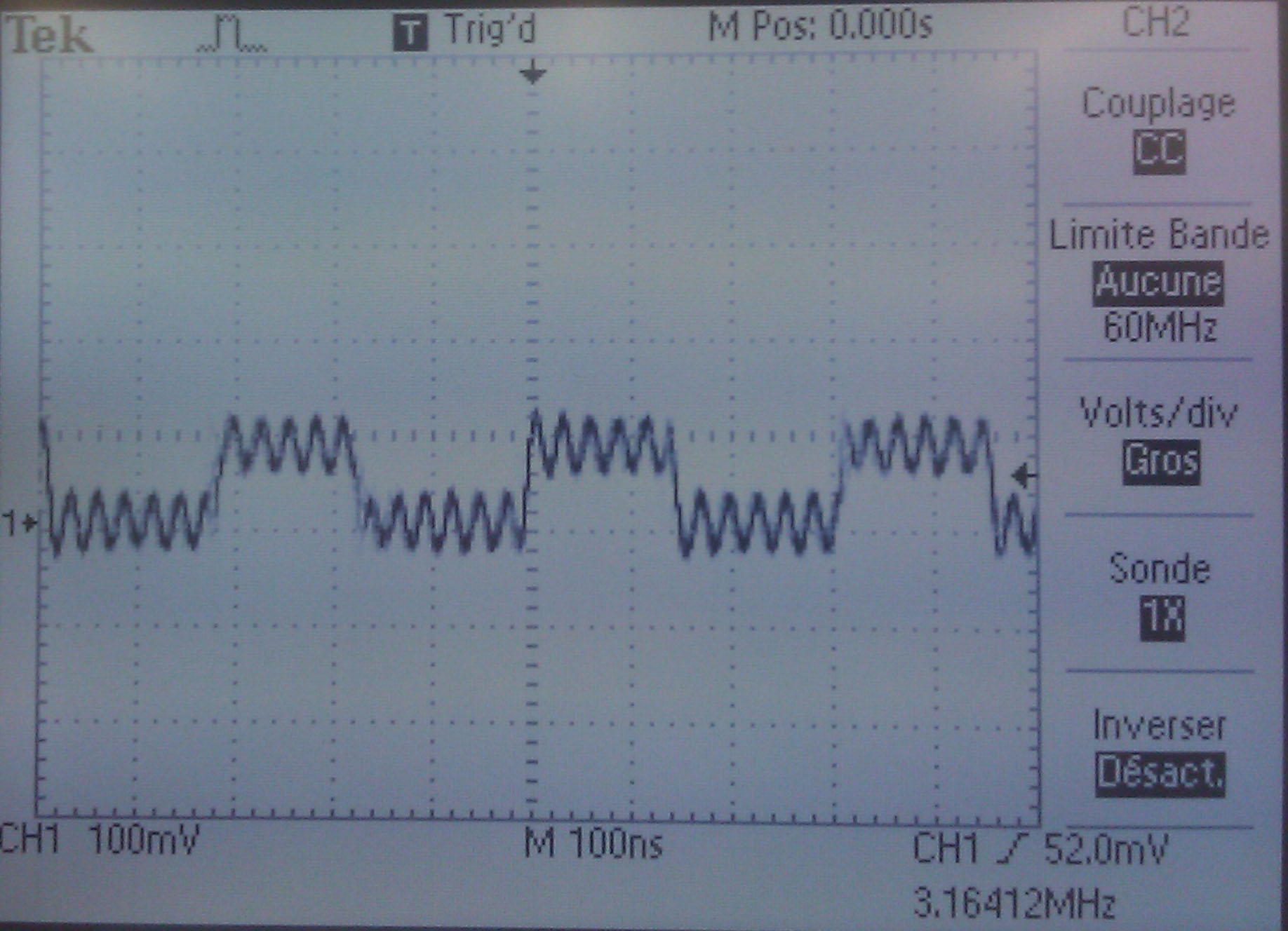
Now, I’ve got a very strange signal on the scope:
And after a while, It looks like the DSP stop working: I see the power consumption going from 240mA to around 100mA for the whole board (on the 1.26V). For code composer, the code is still running, untill I hit “pause”, and get:
Error:
Trouble Halting Target CPU:
Error 0x00000024/-1142
Error during: Register, Execution,
Processor blocked debug accesses. An operation was attempted while the CPU was in a non-debuggable context. To continue to honor the debug context, press Cancel. To force debug access, press Rude Retry.
Then, If I hit resume:
Can't Run Target CPU:
Error 0x00000020/-1141
Error during: Execution,
Processor communication timeout.
It is recommended to RESET EMULATOR. This will disconnect each target, perform an emulation reset, and then reconnect each target. Power cycle the target board before continuing.
And the processor seems looping in this code:
ff869f: f25100019c05 BAND port(#09c05h),#1,TC1
ff86a5: 0474f7 BCC #0xff869f,!TC1
ff86a8: a6519c00 MOV port(#09c00h),T2
Any idea of what’s happening? Electrical problem?
Thanks a lot!