


Hi, guys, i have difficulties in using DM36XX's VPBE module. I want to display a picture on a lcd using the vpbe's
osd bitmap window 0. The lcd supports the rgb888 format, so i orgnize the picture in ddr memory in this format.
That is, the osd bitmap win0's input data src is in rgb888 format and the venc's output data format is in rgb888
too. But the picture displayed on the lcd looks wrong, so many contour lines in it! Something must be wrong!
I am confused! I know that in vpbe, the RGB data from external memory is converted into YCbCr data within the
OSD module and the YCbCr data is converted back to RGB data in venc module before outputting to lcd. The issue is
the result of the conversion? any advises will be appreciated!
I have verified:
1> the input data src is right, the 24-bit RGB888 data is stored in DDR2/mDDR in 32-bit words. Within each 24-bit element,
the blue value is in the least significant byte, followed by the green, then the red byte. The MSByte is not used.
2> some of the key register configuration:
PINMUX0: 0x00fd0000
PINMUX1: 0x002a5555
PINMUX2: 0x0000009a
PINMUX3: 0x015affff
PINMUX4: 0x45547dff
OSDWIN0MD: 0x00005039
VMOD: 0x00002011
3> from HW view, the pins are configured in the right way and perform well, i verify this by:
a. make black & white bar using yuv422 data in format that y increases from 0 to 255 by step one pixel to pixel,
u and v is 0x80. so the r,g,b value is same as y, so measure the bit0-bit7 data lines, signal on the bit7 data
line should has the lowest frequency and bit0 the highest.
b. venc clk is 27MHZ, frequencies measured are:
bit7: 0.105M
bit6: 0.211M
bit5: 0.422M
bit4: 0.844M
bit3: 1.689M
bit2: 3.379M
bit1: 6.76M
bit0: 13.5M
4> output CVBS signal and convert to rgb888 to the same lcd screen, everything is good, so the issue is not come
from the screen.
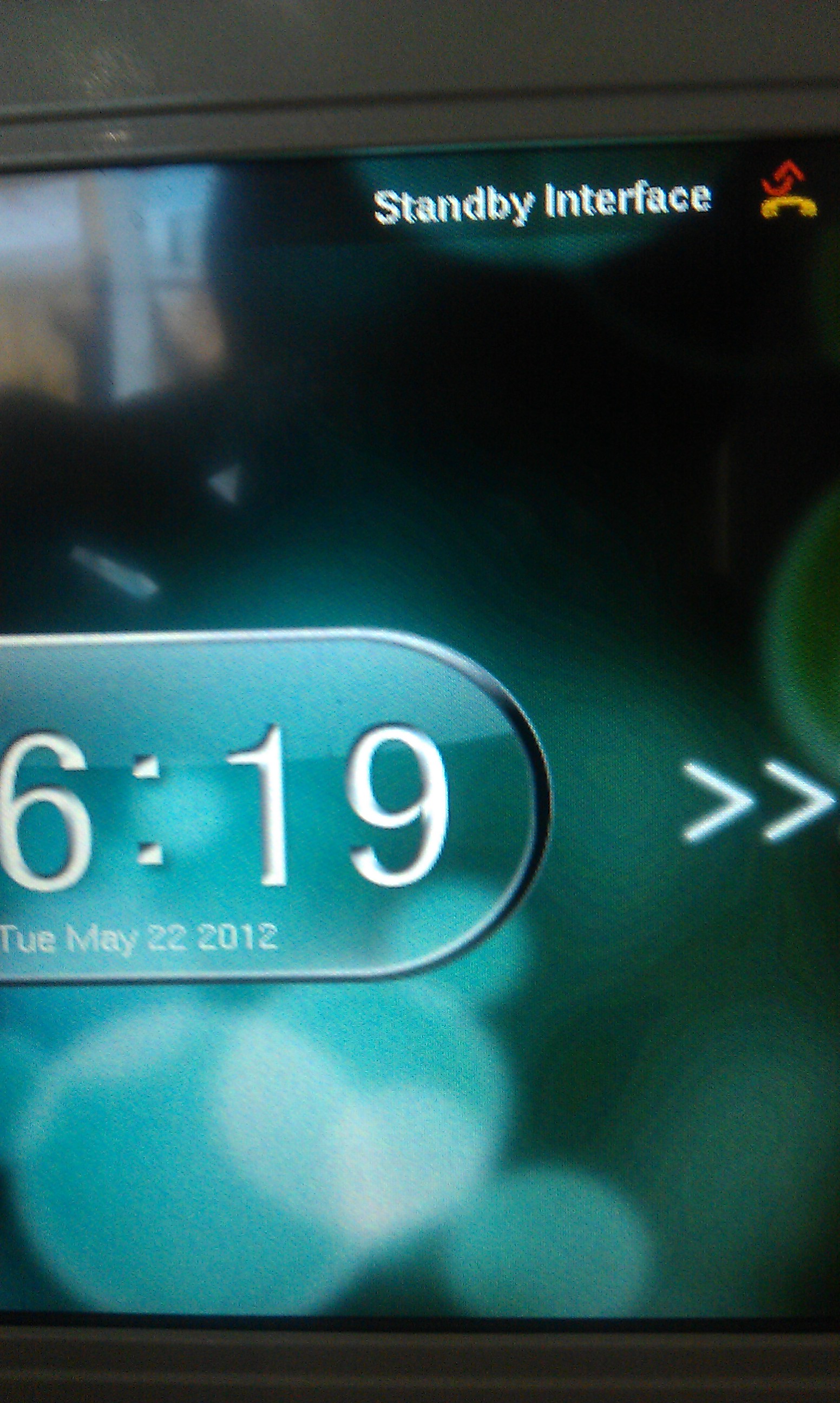
the ugly picture:


