This thread has been locked.

If you have a related question, please click the "Ask a related question" button in the top right corner. The newly created question will be automatically linked to this question.

SPI data missing

Other Parts Discussed in Thread: TMS320C6747

I was using two 6747 communicating through SPI, 4-pins with SCS, 30MHz.

The slave receive data using EDMA, but I find nearly half of the data are missing, the successfully received words are correct.

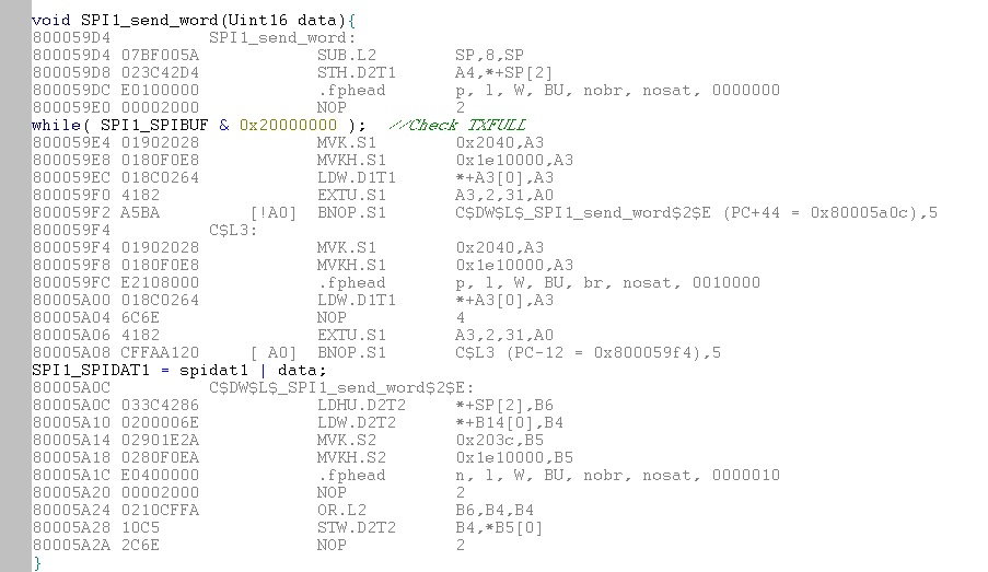
The master part I use a function to send a word in succession, which goes as below:

void SPI1_Send_Word(Uint16 data)

{  while(SPI1_SPIBUF&0x20000000);  //check TXBUFF

   SPI1_SPIDATA1 = spidat1 | data;

}

What's the length of transmit buffer? only one word?

If TXBUFF is set 1 after a word is written to SPIDATA1, does that mean this word needs to be written again? If not, then where maybe cause the problem? 

  • Hello,

    Simple suggestion:

    The CPU and the SPI controller work in different clock domains; depending on how the whole program is optimized, the TXBUFF flag has perhaps not enough time to change when seen from CPU side. In this case, you may try to add some unoptimizable delay before the while keyword, like "asm( " NOP 5" );".

    Jakez

  • Hi,

    Thank you, but it didn't solve the problem although it seems less words are missing.

  • Hello,

    More basic things then :

    - How is SPI1_SPIBUF macro defined ? (to be sure the volatile keyword is used).

    - Can you paste the display of the assembly window for these lines of code ?

    Jakez

  • Dake,

    What SPI driver are you using? Is this a BIOS PSP driver ? Please specify the software package and version. Did you check from the datasheet if this performance is supported .

    Can you reduce the SPI communication speed and see if this issue is resolved? If this works at slower speeds ( eg 10Mhz) , it could indicate the CPU is not able to keep up with the SPI communication speed like Jakez suggested. You can also configure wait delay in the SPI module directly on the master side using WAITEN and specifying wait delay of 0x1-0x3F in the WDELAY in SPIFMT register.

    Have you looked at the clock signal in the osciloscope and checked the signal integrity of the clock at 30Mhz. Also check to see if the start of clock aligns with the data transmitted from the master.

    Regards,

    Rahul

  • Hi,

    All the macro are defined as volatile.

    Here is the assembly code of the function.

  • Hi,

    I use no drivers and configure the registers exactly following the datasheet.

    I slowed the SPI clock and use different DELAYs but it makes no difference.

    I used to check the SCS pin on oscilloscope and it's OK, it changes as the DELAY time changes. Since the received data are correct, I suppose the signal should be good.

    The data missing is irregular and only occurs in mess transmission(8KB lost about 2KB), so its hard to check the signal integrity.

  • Hello,

    All seems fine in code.

    Following Rahul's remark about the SPI speed, TMS320C6747 SPI maximum clock frequency is given to 50 MHz or ASYNC3 / 3, ie main CPU frequency / 6 in standard case (from data sheet, master & slave modes).

    Other suggestions:

    If data lost mean data swallow:

    - EDMA's master priority too low (other masters take precedence over memory access). Check EDMA Event Missing Register (EMR) for the SPI receive event.

    - Check sprz284d.pdf for errata (EDMA3 / L2 stalls cases). If not already the case, try to put the EDMA3 reception buffer in (uncached) shared RAM, to see if a difference.

    If data lost mean bad word received:

    - Check the reception buffer is not cached (or clear associated cache lines before CPU read).

    Jakez

  • Hello Jakez,

    I accidentally used another circuit now it's perfect. I guess the problem is caused by the peripherals. In one of the circuit I used, there is a selector switch:

    Since the BOOT7 pin is used as the SPI1 Clk, I guess it's either because the switcher or the pull-down resistor is too big, ao the clk signal is occasionally missed. Because in the good circuit, there is almost no difference, except uses no switcher and the pull-down resistor is smaller(2K).