This thread has been locked.

If you have a related question, please click the "Ask a related question" button in the top right corner. The newly created question will be automatically linked to this question.

CPRI Interface between 6474 DSP and Xilinx FPGA

Hi e2e.ti users,

I have a strong problem with CPRI interface berween 6474 DSP and FPGA.. Spartan 6 FPGA withCPRI IP Core V4.1 is used.  1X Link (614.4 Mbps) is used. FPGA is the CPRI Master (REC) and DSP is the Slave (RE). 

I tested CSL_6474 AIF example codes on DSP. "aif_cpri_lbk_generic_4x_15bit_short_frame" project referenced and tested on loopback mode. Test passed in 4X mode. Than I configured the DSP to run in 1X rate on loopback mode, test passed again. Than I configured the FPGA to run in 1X rate and looped TX to RX. FPGA passed the test. Both DSP and FPGA work in 1X rate and passed the loppback test. 

In the next step I take out both DSP and FPGA from loopback mode. DSP sending 0-1-2-3-4-5-6-7 continuous integer array to FPGA and FPGA sending 0-1-2-3-4-5-6-7continuous  integer array to DSP. But I received all buffer "00" in FPGA and "FFFF" in DSP. 

 I didnot  find any register on DSP to configure AIF interface as Master(REC) or Slave(RE) ? 

Is there any one run CPRI interface beetween DSP and FPGA? 

I have to solve this problem urgency,

Need your help,

Best Regards,

Ahmet

  • Hi Ahmet,

    If you are trying to implement WCDMA system and your board has both our DSP and FPGA, you should use common reference clock source for AIF and FPGA interface. if you are not using fully synchronized clock between processors, you can not get time sync for any operation. if you already use synchronized clock, they you need to check quality of signal between AIF and FPGA and adjust SERDES analog factors if it doesn't show optimal eye view. if there is no physical issue between two processors, then you need to check time delay between lines and adjust Delta and Phy window (see our UG for more information)

    For external connection test, you need to spend much of your time to match the physical status, clock and timing. you can check TM and RM status registers in AIF if you want to know what happened. everything is in our AIF users guide. please read the document carefully and make your decision how you can start your debugging.

    Regards,

    Albert

  • Hi Albert

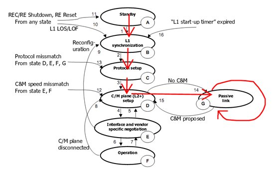
    I have been working for four days on synchronizing DSP and FPGA, but I couldnt handle the problem. I see, L1 synchronization is established  and Protocol version setup is done between DSP and FPGA but than FPGA enter the Passive Mode and the link stay in Passive Mode. 

    I see Tx MAC is in ST2 and Rx MAC is in ST3 all time. SERDES Status every time in PLL0 is locked.  These are some status regs in hex:

    SERDES Status Register :               40
    Rx MAC Link 0 Status Register 0 :  401
    Rx MAC Link 0 Status Register 1 :  fff00000
    Rx MAC Link 0 Status Register 2 :  1000408
    Rx MAC Link 0 Status Register 3 :  1
    Tx MAC Link 0 Status Register :      1

    The main problem seen in "Rx MAC Link 0 Status Register 0 " because of RM_MSTR_FRAME_BNDY_OUT_OF_RANGE bit seems HIGH (Master frame boundary range error is detected).

    And these are my Rx MAC Conf.

    // populate Rx MAC link fields
    aRmCfg[0].bEnableRxMac = TRUE;
    aRmCfg[0].losDetThreshold = AIF_RM_LOS_DETECT_THREH;//255
    aRmCfg[0].maxMasterFrameOffset = AIF_RM_MAX_MASTER_FRAME_OFFSET;//4095
    aRmCfg[0].piOffset = AIF_RM_PI_OFFSET;//1100
    aRmCfg[0].pRxMacCommonSetup = &rmCommonCfg;
    aRmCfg[0].validMasterFrameOffset =  AIF_RM_VALID_MASTER_FRAME_OFFSET;//255

    // RM common cfg
    rmCommonCfg.frameSyncT = AIF_RM_FRAME_SYNC_THRESH; // 3
    rmCommonCfg.frameUnSyncT = AIF_RM_FRAME_UNSYNC_THRESH; // 3
    rmCommonCfg.syncT = AIF_RM_SYNC_THRESH; // 3
    rmCommonCfg.unSyncT = AIF_RM_UNSYNC_THRESH; 33 


    And I see an interesting situation on "Rx MAC Link 0 Status Register 1 " . RM_RCVD_MSTR_FRAME_OFFSET Field always stay in FFF. Rx MAC unit didnt see any VALID_MASTER_FRAME in MAX_MASTER_FRAME. And I give 4095 to MAX_MASTER_FRAME_OFFSET, It is very interesting I think..

    And the last question, DSP must be MASTER or SLAVE? And how can I configure DSP as Master or Slave? There is no configuration register about this in AIF UG.

    Best Regards,

    Ahmet


  • Hi,

    RM_MSTR_FRAME_BNDY_OUT_OF_RANGE error shows that the frame boundary has much delay than you have expected and it is not within your current pi window boundary. and you said you can see RM_RCVD_MSTR_FRAME_OFFSET always shows FFF,  which means it is always out of frame offset count limit (FFF is max count)

    The solution for this problem is checking real incomming frame signal by using your analyzer or use other equipment to know how much delay you have from external device like FPGA or Radio head. based on your new delay calculation, you can set new pi window min,max value  to accept the delayed frame boundary.

    Master, Slave mode can not be supported by DSP. we don't need to be a Master or Slave for Radio interface, if we correctly follow the timing from Frame sync module (with common clock on the board) You may get more knowledge about this from WCDMA spec or CPRI spec.

    Regards,

    Albert 

  • Hi Albert, 

    We have no analyzer or other equipment to know how much delay we have from external device like FPGA or Radio head. Is there any other way to find the delay? And I want to know FSYNC_BRUST (in our configuration ALTSYNC_PULSE) role in Frame Sync Module. In loopback test codes we generate a signal from timer and send it to frame sync module as FSYNC. In our situation, how must I sync DSP and FPGA? What do you think about CPRI Core of FPGA's "nodebfn_tx_strobe signal" (which rising per 10 ms) to connect DSP's ALTSYNC_PULSE input? Can we solve the sync like that?

    I have working on configure PI Offset for a long time, but I couldn't find the correct value.  I planned to read "Rx MAC Link 0 Status Register 1" for get RM_RCVD_MSTR_FRAME_OFFSET value. And when it is different from FFF and 0 it means I am im the correct window. But It is changes acording reading time. I tired to read in "aif_fsevt1_ISR" interrupt which triggered every 38400 chips from FSync event. Is it wrong or when must I read this counter?

    The other problem on FPGA side is when I read CPRI CORE's Status Register I see the link always in "passive link" mode. According to the CPRI Spesification V2.1, we have failed on C&M Plane Setup. How must we setup C&M Plane to work correctly.

  • Ahmet,

    you can use sync signal from FPGA as an input of ALT_SYNC pulse. you may use periodic pulse every 10 ms or just one time pulse to start the frame sync timer. if you see the captured Pi was moving(drifting) within the Pi window, that means your clock sync for radio timer was not fully matched with FPGA's one. you need to use the common input ref clock for both AIF and FPGA on your board. If your FPGA Rx module can detect the incomming frame data from AIF and re-align the clock phase based on the recieved  frame, that problem also can be resolved. (this is what Radio Head module is doing for clock synchronization when they use CPRI) . you can choose any of these two options.

    About C&M plane setup, AIF HW don't care about that. it should be handled by your high level application. AIF just can transfer CPRI control word with L1 inband signals. we don't have any example or recommendation about protocol layer operation. most of our customers have their own way to handle those protocol layer operation but we don't know the detail.

    Regards,

    Albert