This thread has been locked.

If you have a related question, please click the "Ask a related question" button in the top right corner. The newly created question will be automatically linked to this question.

AM335x LPDDR configuration

Other Parts Discussed in Thread: AM3359, AM3356, AM3358

I am trying to bring up a custom board with AM3359 and MT46H64M16LF-6 LPDDR. I am having some issues with data read back.

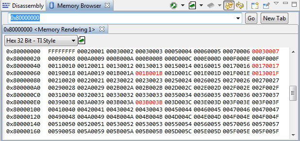
My simple test writes a value to every address (0x00, 0x01, 0x02, etc), and then attempts to read back the value. The lower word for most addresses reads back correctly. The upper word for every memory location reads back as 0x0000.

Every fourth address always reads as a "0x00000000".

If I read the same memory address repeatedly, it does not always return the same value.

I have followed the steps outlined here:

http://processors.wiki.ti.com/index.php/AM335x_EMIF_Configuration_tips

Yet I believe I am still missing something. 

Can anyone out there point me in the right direction?

Thank you in advance. 

  • Update: 

    The Upper word always reads back the same value. For my original test, I was writting 0x0000, but I switched it to 0xDEAD and it reads back 0xDEAD in every upper word as well as every 4th address will read back as "0xDEADDEAD".

  • I have verified that the DDR CK signals are running at 166 MHz. 

  • I modified the timing registers and am having some success. 

    Here is my test: 

    for ( k = 0; k < RAM_LENGTH; k++ )
    {
    pRam[k] = k + ((k+1) << 16);
    }
    for ( k = 0; k < RAM_LENGTH; k++ )
    {
    if ( pRam[k] != (k + ((k+1) << 16)) )
    err[i]++;
    }

    Failures are about 25% of the time, or every 4th 32-bit address. 

    If I use a Memory Browser in CCS set to address 0x8000_0000, with continuous refresh enabled, Some values are changed. These are predominately in at every fourth 32-bit address (offsets of 0x0C, 0x1C, 0x2C, 0x3c...).

    Additionally, the value at address 0x8000_0000 is being returned as 0xFFFF_FFFF.

  • It looks like you still have a timing issue.  Double check both the DDR PHY Register settings (use the Ratio Seed Spreadsheet to obtain the proper values for your board) and the AC timing register settings (use the AM335x DDR Calculation too for the proper values for your board)

    If you think you have all of those correct and are still seeing errors, try adjusting CMDx_PHY_CTRL_SLAVE_RATIO higher:  0x100 or 0x200.

    Regards,

    James

  • Increasing CMDx_PHY_CTRL_SLAVE_RATIO make the issue worse. 

  • Using the Ratio Seed spreadsheet, I get these values:

    Seed values (byte lane)
    WR DQS 0 0
    RD DQS 40 40
    RD DQS GATE 50 4E
    Seed Values
    WR_DQS_SLAVE_RATIO 0
    RD_DQS_SLAVE_RATIO 40
    FIFO_WE_SLAVE_RATIO 4F

    I am using Starerware as a base, so I followed the same code as in the AM335x bootloader DDR configuration:

    HWREG(DATA0_RD_DQS_SLAVE_RATIO_0) = ((0x40 << 30)|(0x40 << 20)|(0x40 << 10)|(0x40 << 0));
    HWREG(DATA0_RD_DQS_SLAVE_RATIO_1) = (0x40 >> 2);

  • I've adjusted the PHY timings to reduce my errors, but I still have errors. For my simple test above, I get occasional failures ( < 1%). However, if I read the memory location again, the expected value is returned.

    Here are my DATA phy seed values:

    #define BSP_EMIF_RD_DQS_SEED (0x12)
    #define BSP_EMIF_WR_DQS_SEED (0x01)
    #define BSP_EMIF_PHY_WRLVL_SEED (0x00)
    #define BSP_EMIF_PHY_GATELVL_SEED (0x00)
    #define BSP_EMIF_PHY_FIFO_WE_SEED (0x80)
    #define BSP_EMIF_PHY_WR_DATA_SEED (0x40)
    #define BSP_EMIF_PHY_LOCK_DIFF (0x00)
    #define BSP_EMIF_PHY_RANK0_DELAY (0x01)

    more work to continue tomorrow....

  • Jay, you shouldn't need to touch any other PHY registers other than the ones explained in the wiki.  Here is an example from an EVM with LPDDR:

    #define  CMD_PHY_CTRL_SLAVE_RATIO        0x80
    #define  CMD_PHY_INVERT_CLKOUT           0x0

    #define  DATA_PHY_RD_DQS_SLAVE_RATIO     0x40
    #define  DATA_PHY_FIFO_WE_SLAVE_RATIO    0x52  //RD_DQS_GATE
    #define  DATA_PHY_WR_DQS_SLAVE_RATIO     0x0
    #define  DATA_PHY_WR_DATA_SLAVE_RATIO    0x40  //WRITE_DATA

    #define  DDR_IOCTRL_VALUE                (0x18B)

    Your values may be different, but these are the only ones that need to be modified. 

    Then, you also need to adjust the AC timing registers in the EMIF controller. based on the memory datasheet values.

    Regards,

    James

  • I got my application running from LPDDR. These are the settings I have for PHY, the do NOT match the values that were generated by the Ratio Spreadsheet.

    #define BSP_EMIF_RD_DQS_SEED (0x12)
    #define BSP_EMIF_WR_DQS_SEED (0x00)
    #define BSP_EMIF_PHY_WRLVL_SEED (0x00)
    #define BSP_EMIF_PHY_GATELVL_SEED (0x00)
    #define BSP_EMIF_PHY_FIFO_WE_SEED (0x4F)
    #define BSP_EMIF_PHY_WR_DATA_SEED (0x40)
    #define BSP_EMIF_PHY_LOCK_DIFF (0x00)
    #define BSP_EMIF_PHY_RANK0_DELAY (0x01)

    The real secret however was setting drive strength to Full. The wiki page says LPDDR should be set to 1/2, with this exception: "Some boards with LPDDR may require full drive strength depending on board size and trace impedances". It would be nice if TI could provide more guidance on that note.


  • Hello JayWhy, JJD,

    I've also been trying to set up my mDDR registers, and I have a question..

    1. The Ratio seed only provided 4 values of the 5 that was mentioned in the chain...the 1 value that it didn't provide is the CMDx_PHY_CTRL_SLAVE_RATIO. This value is seem to be set to 0x80 for mDDR - is that a standard value or does it need to be calculated.

    Thanks a lot for your replies.

    Regards

    Santhosh

  • Hi JJD,

    We recently did an LPDDR setup for the AM335x in StarterWare.  Going over and double-checking the settings we found that some DDR2 settings does not match the description in the TRM, for example:

      #define DDR2_DATA0_RD_DQS_SLAVE_RATIO_0 ((0x40 << 30)|(0x40 << 20)|(0x40 << 10)|(0x40 << 0))

    In the TRM, only bits [9:0] are defined, the rest are reserved.


    If you have a "known good" LPDDR configuration, it would be most appreciated if you can share it along with a part number for the memory used. 


    The SDRAM_CONFIG/PHY_CTRL/REF_CTRL/TIM registers I think we have sorted out thanks to the Wiki pages and the DDR register calculation spread sheet.

    I understand that some values (slew rate, impedance, ...) are dependant on the exact board design so your values may not be directly applicable.


    Thanks,

    Orjan

  • hi jay,

    I have started to work on the board bring up and trying to setup my SW and everything ready for my target board.

    My target board is going to have am3356 processor and LPDDR ram. I went through your post and see that i have to make the similar changes you have made. I was wondering if you can please help me with the changes to make in the board.c files in my board folder in u-boot. i am using beaglebone as my development board untill i get my target board.

    I appreciate your time and help

    Thanks,

    Roy

  • Roy,

    I no longer have access to that data. But the best thing to do is follow the directions on TI's wiki page. That will get you 90% of the way there every time. 

    If you have issues, create a NEW post with your specific questions. TI employees are generally very good about responding.

    You can't really test your changes on the beaglebone, you need your target LPDDR to verify the settings.

    Good luck,

    Jon

  • Hi!

    I am trying to make all the required changes before my target board comes up which will have AM3358 and LpDDR ( MT46H128M16LF). I was wondering if any one can give me a higher level over view of the changes i have to make in the U-Boot directory which will help me in the Board bring up.

    To start with, This is the development i have done so far..

    1) Iam currently working on the beagleBoneblack dev board. I have created a seperate folder in the u-boot/boards/ti/exboard and copied all the files from the am335x folder. I have made changes in the boards.cfg to inlclude the new directory..I could successfully able to build the U-boot and power up the board with the MLO and u-Boot.img files generated from the new folder.  I now have an understanding of how to generate the BSP fiels to bring up the board in U-boot.

    2) Now i have to change the board specifi files for my custom target board..

    with my research so far..I have read about the 

    http://processors.wiki.ti.com/index.php/AM335x_EMIF_Configuration_tips ..( Ratio spread sheet) and also the DDR configuration tool.. 

    I could able to figure out all the values needed for LPddr (MT46H128M16LF) from the data sheet and enter in the ddr config tool. I got the timing values. Which files in the u-boot will these values go?? 

    i am refering he BeagleBone-Xm since it has the lpDDR config....i tried to see the ( u-boot/arch/arm/include/asm/arch-omap3) i understood the emif4.h file/...all the values generated should go in here...so for my new target board with LpDDR should i make this emif4.h in the (u-boot/arch/arm/include/asm/arch-am33xx)?? or should i include in the ddr_defs.h file??

    What exactly are the changes to be made in the U-boot for a target board with am335x and LpDDR

    i appreciate your time

    Thanks,

    Roy

  • Hi Everyone,

    I am working on a AM3358 custom board and we are using LpDDR SDRAM on it..

    We have a problem with the data read from the LPDDR SDRAM address. I am using a BDI3000 Jtag debugger to do my memory tests. 

    These are the observations we made..

    1) When i write 0xffffffff at 0x80200000 address, i see ffffffff written at the address. When i read back the data at the address, i get the same value back. even if i read the data multiple times i read the same data

    UFLOW>md 0x80200000 
    80200000 : ffffffff ffffffff ffffffff ffffffff ................
    80200010 : ffffffff ffffffff ffffffff ffffffff ................
    80200020 : ffffffff ffffffff ffffffff ffffffff ................
    80200030 : ffffffff ffffffff ffffffff ffffffff ................

    2) But, When i write 0x00000000 at 0x80200000, i see that some of the bit values are changing everytime i read.

    UFLOW>mm 0x80200000 0x00000000 16
    UFLOW>md 0x80200000 
    80200000 : ff04ff04      00006004 00006004 00002004 .....`...`... ..
    80200010 : 00000000 00006004 00000004 00006004 .....`.......`..
    80200020 : 00000000 00006004 00000004 00000004 .....`..........
    80200030 : 00000000 00000004 00000004 00006004 .............`..

    3) We performed some memory tests writing some patterns and identified only some bits are inconsistent everytime

    These are the register values we are using..

    config_ddr(200, MT46H128M16LF_IOCTRL_VALUE, &lpddr_data,
    &lpddr_cmd_ctrl_data, &lpddr_emif_reg_data, 0);

     Clock rate = 200

    we got the emif registers from the AM335x_EMIF_config tool according to the RAM timings..

    /*Config tool*/

    #define MT46H128M16LF_EMIF_READ_LATENCY 0x04

    #define MT46H128M16LF_EMIF_TIM1 0x04447289
    #define MT46H128M16LF_EMIF_TIM2 0x10160580
    #define MT46H128M16LF_EMIF_TIM3 0x000000E7
    #define MT46H128M16LF_EMIF_SDCFG 0x20044EA3
    #define MT46H128M16LF_EMIF_SDREF 0x00000618
    #define MT46H128M16LF_DLL_LOCK_DIFF 0x0

    /*ratio spreadsheet
    *
    /

    #define MT46H128M16LF_INVERT_CLKOUT 0x0
    #define MT46H128M16LF_PHY_RD_DQS 0x40
    #define MT46H128M16LF_PHY_FIFO_WE 0x200
    #define MT46H128M16LF_PHY_WR_DQS 0x1
    #define MT46H128M16LF_PHY_WR_DATA 0x40
    #define MT46H128M16LF_RATIO 0x80
    #define MT46H128M16LF_PHY_RANK0_DELAY 0x01
    #define MT46H128M16LF_PHY_WRLVL 0x0
    #define MT46H128M16LF_PHY_GATELVL 0x0

    #define MT46H128M16LF_IOCTRL_VALUE 0x18B

    The RAM is on full drive strength.. are there any registers that should be modified for the LpDDR??

    our trace lengths are 

    Trace Length (inches)
    Byte 0 Byte 1
    DDR_CK trace 1.15361 1.15361
    DDR_DQSx trace 1.04342 1.04074
    Appreciate your time.
    Thanks,
    Harsha