This thread has been locked.

If you have a related question, please click the "Ask a related question" button in the top right corner. The newly created question will be automatically linked to this question.

Mistral DM814x and AM3874 Board

Other Parts Discussed in Thread: AM3874

Hi all,

I have looked at the Mistral DM814x & AM3874 Base Board documentation (gerber) and could not able to confirm the 1st and 2nd impedance requirements.

All my calculation are same for given stackup except the diff pairs on layer 5 and 6. (I am using SaturnPCB Toolkit. http://saturnpcb.com/pcb_toolkit.htm )

Diff pairs on layer 5 and 6 seems assymetrical stripline but my findings are not 90 and 100 ohm repectly for 1st and 2nd requirement.

Could some one help me how to calculate (confirm) 1st & 2nd impedance requirement with SaturnPCB Toolkit or any other free tool ?

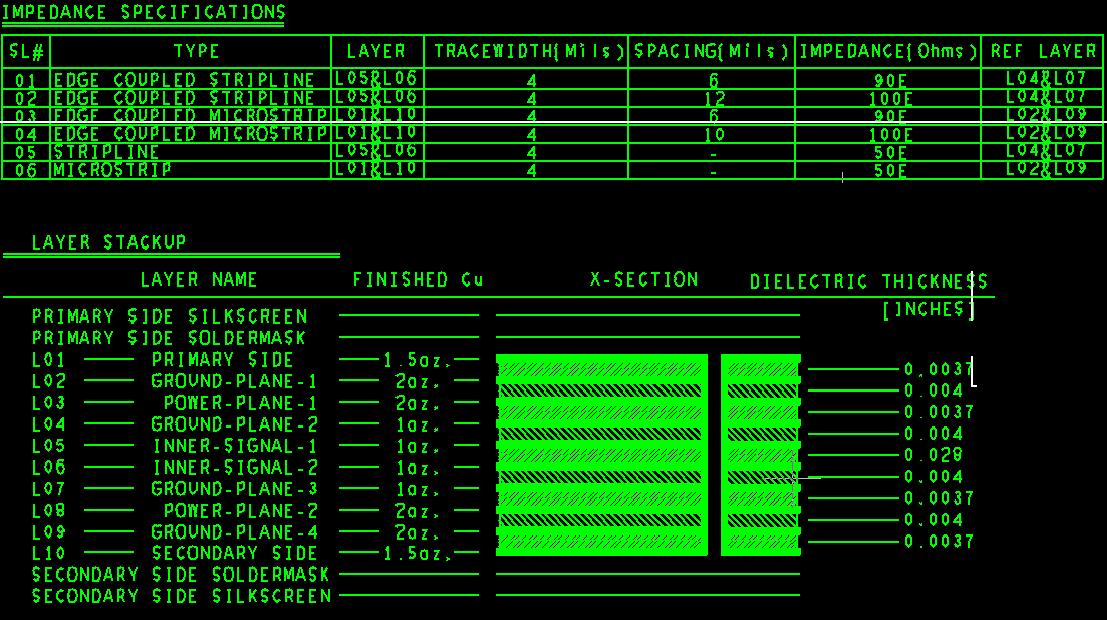
The picture below shows impedance requirements and stackup.

Best Regards.

  • Hi Yilmaz,
     
    I think there is an error in the dielectric thickness between L5 and L6 - it should be 0.0028" instead of 0.028". Then all calculations are fine, especially if you set Er to something like 3.6, which is typical for prepregs most widely used in multilayer PCB's
     
    Best Regards
    Biser
  • Hi Biser,

    Thank you for your time and answer.

    But  the total board thickness (80mil)  and stackup (79.8mil) thickness are the same for 28mil.

    2.8 mil would be appropriate for reference plane bu it will not for signal layers.

    I could not able to see what I am missing.

    Best regards. 

  • Yes, I overlooked the fact that this is the PCB core, so 28mil should be correct. In this case the caculations work out if you reference L5 diff pairs to L4, and L6 diff pairs to L7, and treat them like two 2-layer PCB's. That's probably what they did.

    Best Regards
    Biser
  • OK Sir,

    As you stated I can confirm the calculation if I threat this as microstrip, but is it not true for real signal integrity analysis. 

    This board is running properly. Still it is not clear for me, what I am missing. 

    Best Regards. 

  • Yilmaz, you are right and I completely agree with you. What I did was try to reach the 90R and 100R impedances using the Saturn toolkit and the data provided by Mistral. What is the real situation only Mistral and their PCB manufacturer can say. From my experience usually PCB houses adjust the diff pairs width and spacing directly on the Gerbers to provide the requested impedance with their materials.
     
    It's just an idea that maybe they used the microstrip mode because of the relatively thick 28mil core between L5 and L6, presuming that this is a large enough spacing to block signal interference.
     
    Best Regards
    Biser
  • Hi Again,

    I thank you for your time and responses. I have asked this issue to Mistral support and waiting for their reply.

    Then, I am giong share the real situation if any one interested about this.

    Best Regards.