This thread has been locked.

If you have a related question, please click the "Ask a related question" button in the top right corner. The newly created question will be automatically linked to this question.

DM368 CVBS burst amplitude level

Hello,

we have an design with a DM368 in an HD IP camera.

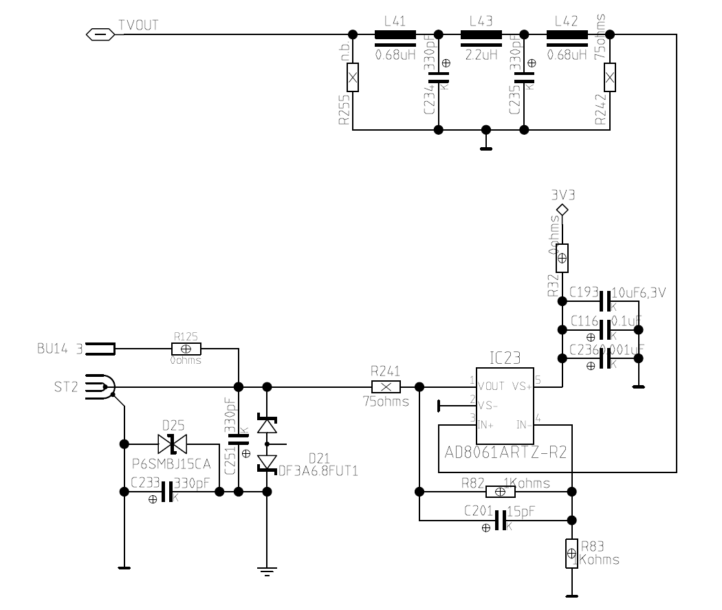
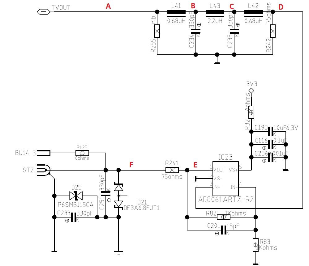
For camera setup support and compatibility reasons to old devices, weg have included an CVBS analog output.

The problem now is, that we must provide correct NTSC and PAL output (switchable via our software) capability and our customer comes from the good old analog video technology with high-end quality.

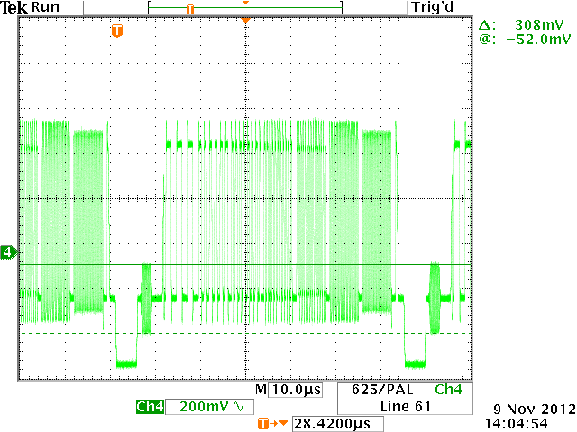
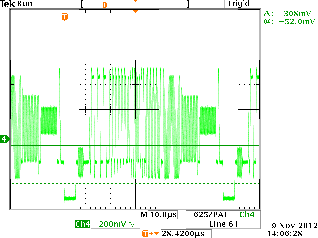
So he complained that the burst amplitude in PAL is not correct and therefore also the colors and the phase (vectorscope).

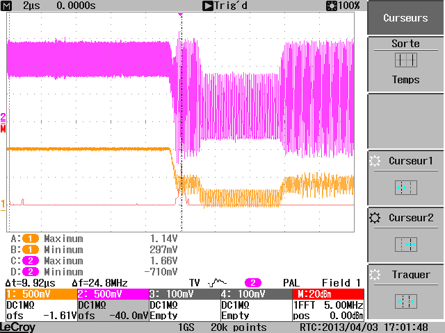
When I measure this, I can see that the signal and sync level between PAL and NTSC is outputted correctly, but the burst is only around 240-250mVpp in PAL.

In NTSC it is correct approx. around 286mVpp.

VENC.CVBS is 0x23 in PAL and 0x00 in NTSC

VENC.VMOD is 0x43 in PAL and 0x03 in NTSC

The register which sets the burst amplitude ist VENC.VMOD.TVTYP, when I change this single 2-bits between 00 (=NTSC) and 01 (=PAL) then the burst amplitude changes between the correct NTSC and the wrong PAL amplitude.

How can I achieve the right analog value in PAL+NTSC?

I did not found any register where I can change this.

Is this a bug from the DM368?

Thanks for any hint,

Erich Voko

  • Sorry for the delay in getting back to you.

    Could you please send your output schematics? Is there an external filter added to the PAL/NTSC output?

    BR,

    Steve

  • Hi Steve,

    thanks for the reply, attached you find the complete output schematics, the signal TVOUT is directly connected to the DM368 pin A10.

    At the moment C201 is not stuffed and C234 is changed to 100p, both changes gives slightly better frequency response (simulated filter) which helps for higher Burst amplitude.

    Reference voltage is 500mV, IDACOUT/VFB/IREF Pins are the normal resistor values.

    Kind Regards,

    Erich Voko

  • Hello,

    I'm sad that there is no feedback here, because our customer makes preasure to solve the problem.

    We will have a last small relayout in november (emc surge issues) and if this is a hardware problem it has to be fixed now.

    Yesterday I measured 2 pcbs, one represents the "normal" behaviour we see in the factory that the burst level is too low and a "golden sample" for video out which has correct values. Idea was to find differences with the golden sample to locate the problem.

    Firmware on both pcb's are the same, also all markings on the Chip (DM368ZCEDF 12AGFIW 570 G1).

    I measured the values of all components in the area of the video DAC (to be sure that there are no stuffing differences or wrong components).

    I checked all voltages (Reference 500mV, 1.8 and 1.2 (=1.35)V for the DAC), its all the same between the pcb's and correct values.

    Then I measured the TVOUT without the additional buffer and filter (desoldered L41 and stuffed R255 with a 75E resistor), all measurements done with a 2GHz scope with active probe on R255 to GND, self generated 100% colorbar on the TVOUT.

                     bad pcb                        good pcb

    PAL         264mVpp      burst       316mVpp

                     310mV           sync       306mV

                     706mV          white       714mV

    NTSC      280mVpp      burst       296mVpp

                     296mV           sync        296mV

                     722mV          white       724mV

    So the problem is that the sync and white level is approx. the same between the 2 pcb's (in PAL and NTSC), only the burst amplitude is different.

    What's also very strange is that the bad pcb has a higher burst amplitude in NTSC compared to PAL (what is wrong), the good one is right (a little bit to much amplitude, but in the followed filter this will be lowered by some mV's, so in the end the level is right).

    The problem with too low burst is, that the color saturation on an analog monitor depends from the burst amplitude (also seen very good on an vectorscope).

    Please help us to solve the problem, we think it is a problem of/or in the DM368, we have no idea how to slove it.

    Above is the DAC part (DM368) of our schematics.

    Greetings,

    Erich Voko

  • Erich,

    I apologize for the delayed response. For some reason I did not receive a notification from our system that you had replied with the schematics.

    I will look at this and get back to you ASAP.

    BR,

    Steve

  • Erich,

    You mention L41 and stuffed R255 but I can't see them on the schematic you posted.Can you please post the complete output path part of the schematic.

    The fact that the DC levels are correct but the AC levels implies there is something capacitive in the output path causing the issue.

    PAL has a higher frequency color burst, so if the issue is caused by stray/incorrect capacitances then it would be affected more.

    Are you able to display a multiburst image so that we can see if the issue is really something which is frequency dependent?

    BR,

    Steve

  • Hi,

    the L41 and the R255 is in the upper schematics, please scroll up into my 2nd post, there you can find the output buffer with filter.

    We can make a multiburst pattern in a testfirmware.

    Thanks for your help,

    Erich

  • OK, sorry. I missed that, sorry.

    I can't see anything obviously wrong.

    You did mention that changing the filter cap helps but this contradicts a little with the second test where you removed L41 and populated R255.

    Can you put your filter back and then compare each node from the DM output through to the connector output between the good and the bad boards to see if you can spot the point at which the signals diverge from each other?

    BR,

    Steve

  • There was supposed to be an image here !!!

  • I have just run a spice analysis on the filter and it will be down by 10%+ at 4.43MHz for PAL and by about 5% for NTSC at 3.58MHz.

    The standard reference levels are 306mV for PAL and 285mV for NTSC, therefore with a fully compliant output from the DM passed through the filter you would get 275mV for PAL and 270mV for NTSC. I would expect this attenuation on all boards, even the 'good' board.

    Using the 'good' PCB levels as the starting point I would expect to see PAL give 284mV and NTSC give 281mV after the filter.

    The specification allows for +- 5IRE in these levels which equates to +-35.7mV. Your measurements are off by 42mV (no filter) and 11mV with the filter there.

    The phase is also distorted slightly by this filter, but that might not really be an issue since the carrier is a fixed frequency.

    I don't know why you are seeing different boards with different measurements.

    Is it possible that there is an assembly issue such that the capacitors on the 'good' board have connectivity issues?

    The measurements mentioned above comparing a good board with bad will also helpful, and will also validate the filter attenuation calculations.

    BR,

    Steve

  • Hi Steve,

    thanks for your answers.

    I did some tests and measurements yesterday, but no improvement, so no direct answer to your questions, sorry (measuring problems).

    I found a measuring problem with the active probe, compared to a direct soldering without probe (1:1) and a passive probe (1:10), it measures a higher voltage level.

    Checked also with a calibrated generator and a Tek vectorscope, use now an other equipment to measure.

    So my values in the above posts are to high :-(

    I found also 2 other cameras with a good CVBS burst level, so I will continue today with measurements and comarisons.

    What I am not understanding is the difference in the direct DM368 output level, there should be no impact of capacitance and tolerances and no filter in the signal flow.

    Can you focus on this question?

    So I disabled the filter and opamp and measured directly the DM368 output  with 75E termination.

    (The filter can be used to finetune the signal in the end.)

    We use an DM368 with face recognition (for future use), maybe there is an difference to the normal DM368?

    Thanks and best regards,

    Erich

  • Erich,

    The capacitances are extremely critical since the poles are currently very close to the color burst carrier frequency.

    It is critical to compare the input to the filter with the output of the filter.

    Can you try removing all the capacitors from the filter (leave the inductors since they will do nothing when the capacitors are removed?

    I have some reservations regarding the filter.

    There is no difference in the video output between devices with and without face recognition.

    BR,

    Steve

  • Hi Steve,

    yes the filter is critical in components tolerances.

    But why is there a difference with not stuffed L41?

    Then the filter is not in the signal chain because I measured on (only for this measurement stuffed) R255?

    In this condition I measure only the direct output of the DM368.

    This is my biggest question.

    Best regards,

    Erich

  • Erich,

    I agree with you that your test removing L and loading with 75R should be a good test, but I am wondering if there is something else going on with the PCB that we can't see.

    How many different PCBs have you tried this on?

    Are the other levels correct? Is it only the color burst which is attenuated?

    I can't think of any reason why the amplitude would be off like this just for the PAL color burst.

    As an experiment you could try setting NTSC, then change just the carrier frequency to see if it becomes attenuated (on a bad board). If yes, then there is most likely something on the board creating a filter. (Not 100% sure if this is programmable enough to do this since I am not familiar with all the VENC registers)

    A multi-burst pattern for both NTSC and PAL would also be very telling. (this would help determine if it is purely a color burst issue or a general bandwidth issue)

    It is possible there is a silicon issue but we have not had any other comments regarding this so is a low probability.

    BR,

    Steve

  • Hi,

    our customer made a quantity of approx. 30pcs for a first project on an airport.

    There was no good piece.

    Here in my office I have 3 good ones, all from the same batch of production where the 30 comes from.

    I will check if I can get the multiburst image on the output.

    BR,

    Erich

  • The measurements at points A thu F mentioned above would also be informative too.

    As I mentioned previously I would expect the PAL color burst to be attenuated simply due to the filter.

    BR,

    Steve

  • Hi Steve,

    I found a pcb where this phenomen changes afer some reboots. So its good and bad on the same pcb with the same settings without touching anything.

    Maybe there is a timing issue in or our application.

    The startscreen (in the kernel there is the TV-out active during booting, showing a Tux and boot messages) is always right from the levels.

    Also when the device showes the bad levels, in the bootscreen the burst is allright.

    We use kernel 2.6.32.59-davinci1 and Poky filesystem.

    Attached you find 2 screenshots from the same device with the added multiburst testpicture.

    I will investigate this with a software engeneer on monday.

    The register values of the VENC are the same between good and bad.

    BR

    Erich Voko

  • Hmm, VERY interesting.

    It does certainly point to some configuration issue then I think, given that the boot logo is always correct. This means it isn't a hardware issue (i.e. not a silicon variation).

    I can't think of anything else that could cause this though.

    The roll-off is pretty drastic though and is certainly the cause of the burst issue.

    The burst, therefore is now relegated to a symptom and the really issue is frequency response.

    When you reboot, is it a hard reboot (power removed) or a soft reboot?

    BR,

    Steve

  • Hi,

    reboot is an hard-reboot.

    Softreboot will also trigger a watchdog -> Reset.

    Will check today with an software-guy.

    BR

    Erich

  • Hi,

    we made a lot of test.

    We can say, that the problem only occurs in PAL output mode.

    In NTSC its always correct.

    When we change the output of the kernel to PAL, we can see the problem directly after starting the kernel (2.6.32 from Ti).

    So we can say it's not our application.

    We never see the problem after the booting that it changes, so when it boots with a lower ampltude, it stays to low and vice versa.

    Only a dis- and reconnect on the power supply can change.

    So we will try a older kernel 2.6.18 from appro (our customer says that with the appro reference design it never happened), the engineer is doing that tomorrow.

    Do you have an idea what could get wrong on startup?

    BR

    Erich

  • Hi Steve,

    we found something but we do not know what/why!

    In the VDAC_CONFIG register the bit PWDNZ_TVDETECT was enabled.

    When disabled (like in an older kernel version, we merged something months ago), everything is ok.

    Also there was some time ago a problem with a small clock signal overlayed on the CVBS out which was repaired with the bit 28 in the reserved area.

    Also on newer kernel versions in the first reserved area (bit 6-18) the data changed.

    So do you have more information what's in this reserved area? Its not documented but it hase impact and values change in kernel versions.

    Also why this is a problem for the PWDNZ_TVDETECT?

    The function behind that is useless in our design because of the buffer, so the DM368 cannot see the presence of the load of a TV.

    So its clear that we change this to disable but why makes this a problem?

    BR

    Erich

  • Erich,

    Thanks for the information.

    I am glad you have at least found a solution for your specific issue.

    At the moment I can't comment on why these register controls have this effect unfortunately.

    BR,

    Steve

  • Hello,
    I post a message here, because I also found strange behavior with CVBS and TVDETECT bit in VDAC_CONFIG registry.
    I am working on DM368 and I use the version 4.02.00.06-evm ti-dvsdk_dm368 on a custom board.

    During my development, I found that the analog output was very dirty. By connecting an oscilloscope, I found the following:

    Channel 2, the signal taken directly from the TVOUT pin.
    Channel 1, the signal on the BNC output (between the two there is a filter in accordance with the datatsheet)

    It can be seen that the bottom of sync is extremely noisy and this noise is stronger as the voltage is low.

    After reading this post, I wanted to see the state of bit PWDNZ_TVDETECT in my setup. The default registry value of VDAC_CONFIG was 0x081141CF.

    PWDNZ_TVDETECT was already disabled.
    I try activating it (write 0x081141DF on VDAC_CONFIG) , and magically the noise completely disappeared.

    I have not been able to find more information on this feature, but what is certain is that it has a very powerful effect.
    If someone complementary information, with pleasure.

  • Hi,

    long time ago we had also a kind of 13,5MHz noise on the complete video signal including burst.

    We got rid of it with DM368 bit 0 adress 0x01C71E38 (YCCCTL) change to "1".

    This was a kernel change when we moved from 2.6.18 to 2.6.32.

    Changed to the old value from 2.6.18 and the problem gone.

    Maybe its the same in your software.


    BR

    Erich Voko